
Improved vacuum rake type dryer

A rake dryer and vacuum technology, used in non-progressive dryers, drying solid materials, heating to dry solid materials, etc., can solve the problems of high electricity and steam consumption, unstable product quality, and low production efficiency. , to achieve the effect of reducing processing cycle, improving product quality and improving production efficiency

Inactive Publication Date: 2009-06-24
董辉
View PDF5 Cites 15 Cited by
  • Summary
  • Abstract
  • Description
  • Claims
  • Application Information

AI Technical Summary

Problems solved by technology

[0002] Vacuum rake dryer is a traditional drying equipment with simple structure, convenient operation and strong applicability. It is mainly used in the fields of medicine, food, light industry, chemical industry, etc. When the traditional vacuum rake dryer dries the material, the material enters the shell from the feeding device, and is stirred by the rake teeth that are constantly rotating forward and reverse, and the material along the axis Walking back and forth, the surface in contact with the inner wall of the shell is constantly renewed, and is indirectly heated by the steam of the shell, evenly stirred and crushed by the rake teeth, so that the water in the material is vaporized, and under the action of the vacuum system, the water inside the material is Parts and surface moisture are more advantageously discharged, and the vaporized water is discharged from the outlet of the vacuum pump through the dry dust collector, wet dust collector and condenser, but since the heating is through steam (hot water) only to a single surface of the shell Circular heating, the material is heated with the continuous contact with the surface of the shell, so that the moisture in the material is vaporized and contacted by heat, because the heating is only provided by the surface of the shell, which results in a long time for the temperature to be transmitted to the entire material and low production efficiency. The energy of electricity and steam consumes a lot relatively, and because the temperature source is on the surface of the shell, there is only a single heat cycle, and the temperature penetrating into the middle of the material is very different from the temperature of the shell wall. There is a phenomenon of material accumulation, it is not easy to fall off, and the product quality is unstable due to agglomeration

Method used


Image

  • Improved vacuum rake type dryer

Examples


Embodiment Construction

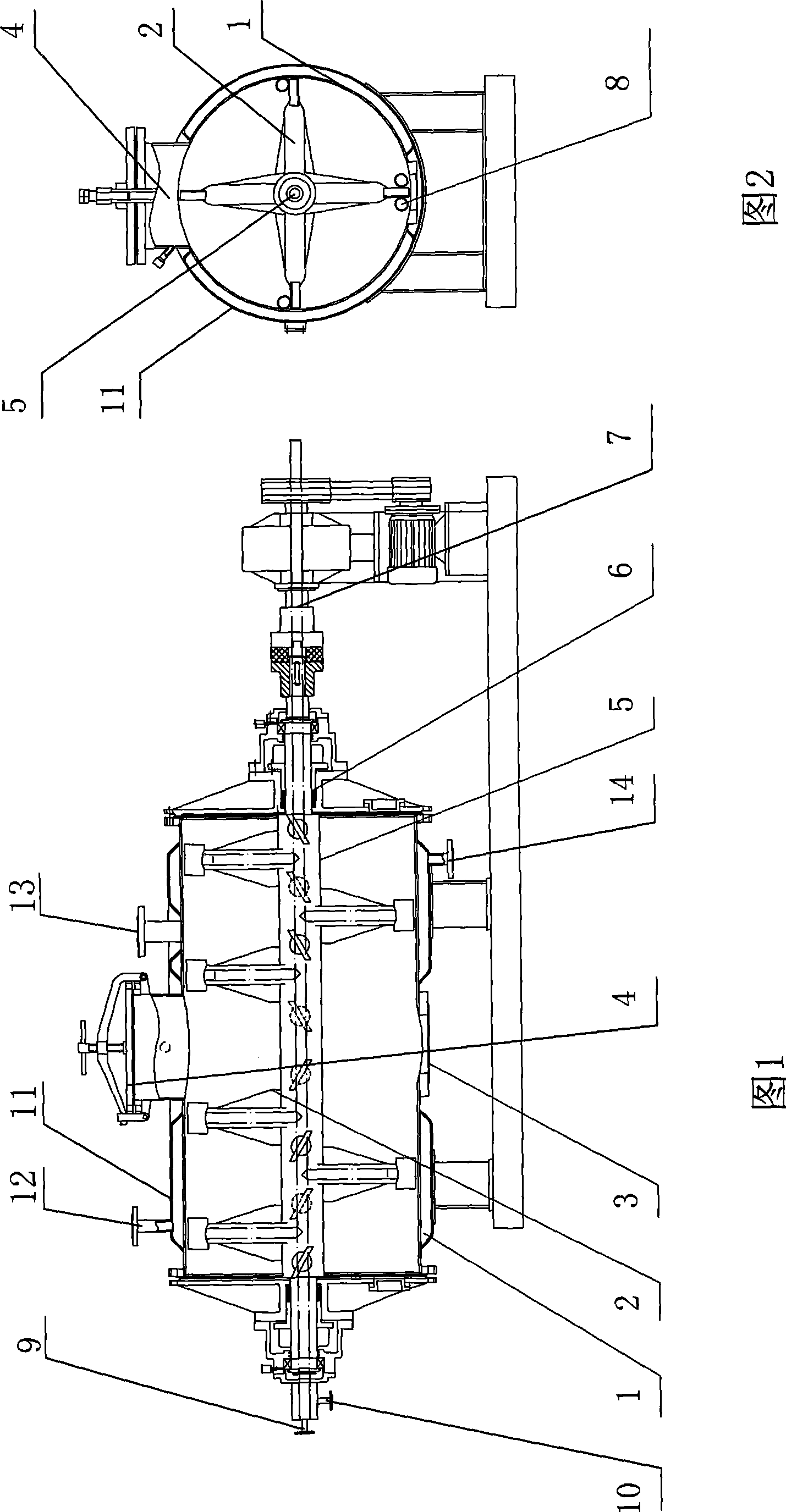
[0009] see picture 1, figure 2 , the present invention comprises housing 1, rake tooth 2, stirring shaft 5, transmission device 7, and rake tooth 2 is fixed on the stirring shaft 5, and stirring shaft 5 runs through housing 1, and stirring shaft 5 is connected with transmission device 7, and housing 1 is provided with a jacket, the stirring shaft 5 and the rake tooth 2 are hollow tubes, and the stirring shaft 5 and the rake tooth 2 are connected internally; the outer end of the stirring shaft 5 is equipped with a steam inlet 9 and a steam outlet 10. In the figure, 3 is a discharge device, 4 is a feeding device, 6 is a sealing device, 8 is a crushing rod, 11 is a jacket, 12 is a jacket steam inlet, 13 is a vacuum port, and 14 is a jacket steam outlet. mouth. The feeding device 4 and the discharging device 3 are arranged above and below the casing 1 respectively; crushing rods 8 are placed in the casing, and a crushing rod 8 is placed between every two rake teeth 2 .

[0010] ...


PUM


Abstract

The invention provides an improved vacuum harrow dryer with energy conservation, high efficiency, short heating time, high production efficiency and stable product quality. The vacuum harrow dryer comprises a casing body, harrow teeth and a transmission device, the harrow teeth are fixed on a stirring shaft, the stirring shaft is penetrated in the casing body, the stirring shaft is connected with the transmission device, the casing body is provided with a jacket, and the jacket is provided with a steam inlet and a steam outlet. The vacuum harrow dryer is characterized in that the stirring shaft is a hollow pipe, and the steam inlet and the steam outlet are formed at the external end parts of the stirring shaft.

Description

(1) Technical field [0001] The invention relates to the field of material drying equipment, in particular to an improved vacuum rake dryer. (2) Background technology [0002] Vacuum rake dryer is a traditional drying equipment with simple structure, convenient operation and strong applicability. It is mainly used in the fields of medicine, food, light industry, chemical industry, etc. When the traditional vacuum rake dryer dries the material, the material enters the shell from the feeding device, and is stirred by the rake teeth that are constantly rotating forward and reverse, and the material along the axis Walking back and forth, the surface in contact with the inner wall of the shell is constantly renewed, and is indirectly heated by the steam of the shell, evenly stirred and crushed by the rake teeth, so that the water in the material is vaporized, and under the action of the vacuum system, the water inside the material is Parts and surface moisture are more advantageo...

Claims


Application Information

Patent Timeline
IPC IPC(8): F26B11/14F26B3/22
Inventor 董辉王辉
Owner 董辉
Features
  • Generate Ideas
  • Intellectual Property
  • Life Sciences
  • Materials
  • Tech Scout
  • Unparalleled Data Quality
  • Higher Quality Content
  • 60% Fewer Hallucinations
Learn More