Method for cleaning air cooler as well as device for carrying out the method, and air cooler equipped for the same

An air cooler, air cooling technology, applied in the direction of cleaning heat transfer device, engine cooling, installation, etc., can solve the problems of increased maintenance and maintenance costs, unfavorable service life, accelerated corrosion of cooler components, etc., and achieves small structural size. , to avoid corrosion, the effect of reliable removal

Inactive Publication Date: 2009-06-24
MAN DIESEL & TURBO FILIAL AF MAN DIESEL & TURBO SE TYSKLAND
View PDF1 Cites 2 Cited by
  • Summary
  • Abstract
  • Description
  • Claims
  • Application Information

AI Technical Summary

Problems solved by technology

However, according to experience, chemically active substances accelerate the corrosion of cooler elements, ...

Method used


Image

  • Method for cleaning air cooler as well as device for carrying out the method, and air cooler equipped for the same
  • Method for cleaning air cooler as well as device for carrying out the method, and air cooler equipped for the same
  • Method for cleaning air cooler as well as device for carrying out the method, and air cooler equipped for the same

Examples


Embodiment Construction

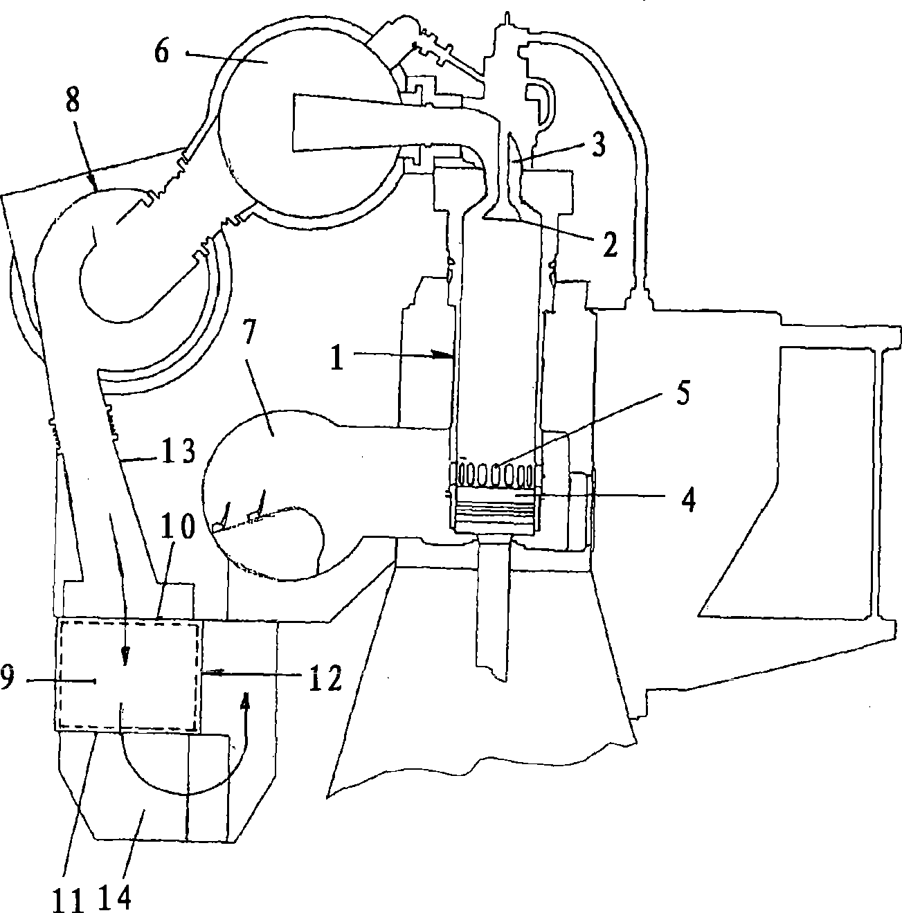
[0028]An important field of application of the invention is large engines, such as large two-stroke diesel engines, preferably provided with an exhaust gas turbocharger. Engines of this type are used extensively in marine propulsion. exist figure 1 An engine of this type is shown in . Although the invention will be described by means of this preferred embodiment, it should not be construed as limiting the invention thereto.

[0029] as figure 1 Engines of the basic type generally comprise a plurality of cylinders 1 arranged side by side in rows, said cylinders having an upper exhaust gas outlet 3 controllable by an exhaust valve 2 and a lower one controlled by pistons 4 which move up and down. The air inlet slit 5 is used to supply the necessary air to the working chamber through the air inlet slit. The exhaust gas outlets 3 of the cylinders 1 lead into an exhaust gas manifold 6 . The air inlet slit communicates with a distribution pipe 7 . In naturally aspirated engines...


PUM


Abstract

The invention relates to an air loaded air cooler (9) such as an engine. The air cooler has an area (15) designed to a heat exchanger arranged between an air inlet and an air outlet. The area contains a plurality of vertical flow passages (18) which is crossed by an uncooling air from up to down and limited by an outer cooling surface, wherein a high reliability and a long service life can be realized by that the area (15) designed to the heat exchanger is rotated about a half rotation around an axis which traverses the uncooling air and extends along the flow direction from up to down, and the area (15) designed to the heat exchanger can be loaded by the uncooling air crossing the area from up to down at an up and down reversal position which is rotated about a half rotation.

Description

technical field [0001] The invention relates to a method for cleaning an air cooler according to the preamble of claim 1 and a device for carrying out the method according to the preamble of claim 12 , and to a Air coolers constructed for this purpose as described in the preamble of 31. Background technique [0002] Contaminants (impurities) in the form of dust particles or the like brought into the air cooler by the air to be cooled can narrow and block the flow channels assigned to the air. According to experience, such narrowings or blockages are already formed at a small distance from the inlet side, i.e. from the upper side of the air cooler, where condensation water usually also starts to form, so that the pollutants are humidified and can interact with each other. Gather into a viscous substance. As the flow channel narrows or becomes progressively more clogged, a progressively higher pressure drop occurs. Once the pressure drop has reached the specified level, the...

Claims


Application Information

Patent Timeline
IPC IPC(8): F28G13/00F01P11/12F02B29/04
CPCF01P2011/063F02B25/04F28F2280/02F28F2280/10Y02T10/146F01P2060/02F28G13/00F02B29/0462F02B29/0468F28F17/005Y02T10/12
Inventor C·N·尼尔森
Owner MAN DIESEL & TURBO FILIAL AF MAN DIESEL & TURBO SE TYSKLAND
Why Eureka
Try Eureka