Low-pressure difference linear voltage stabilizer with high power supply rejection ratio

A high power supply rejection ratio, low dropout linear technology, applied in the direction of instruments, electric variable adjustment, control/regulation system, etc., can solve the problem of small main zero point of PSRR, achieve the effect of improving PSRR characteristics and maintaining stability

Active Publication Date: 2009-06-24
FREMONT MICRO DEVICES SHENZHEN LTD
View PDF0 Cites 23 Cited by
  • Summary
  • Abstract
  • Description
  • Claims
  • Application Information

AI Technical Summary

Problems solved by technology

[0004] The present invention aims at the above-mentioned problem of prior art, proposes a kind of low dropout linear regulator (LDO) with high power supply rejection ratio (PSRR), can

Method used


Image

  • Low-pressure difference linear voltage stabilizer with high power supply rejection ratio
  • Low-pressure difference linear voltage stabilizer with high power supply rejection ratio
  • Low-pressure difference linear voltage stabilizer with high power supply rejection ratio

Examples


Embodiment Construction

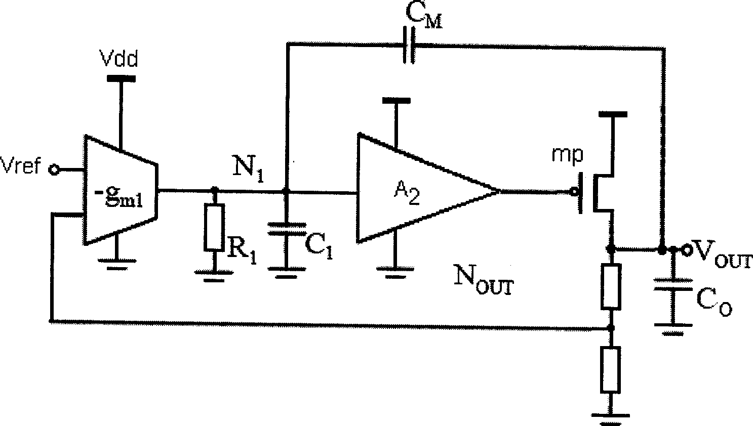
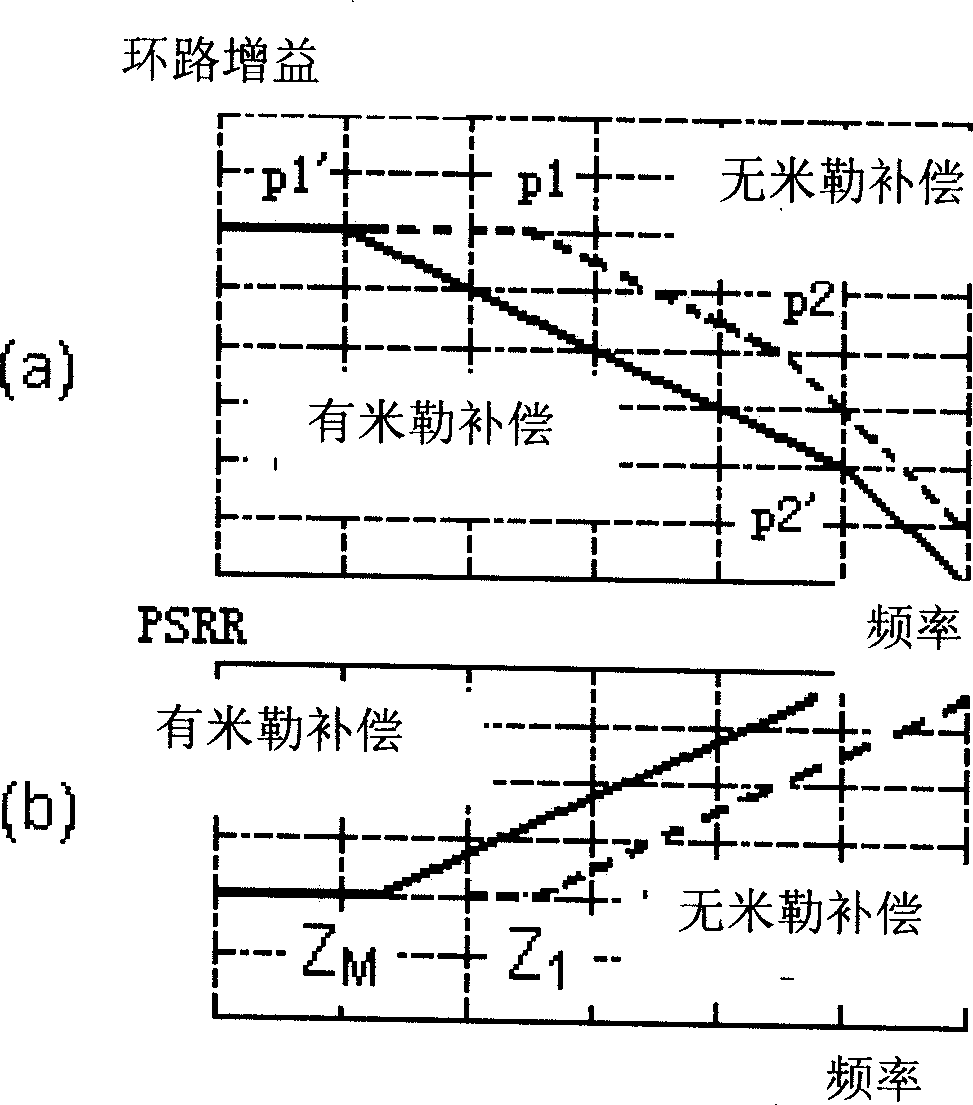
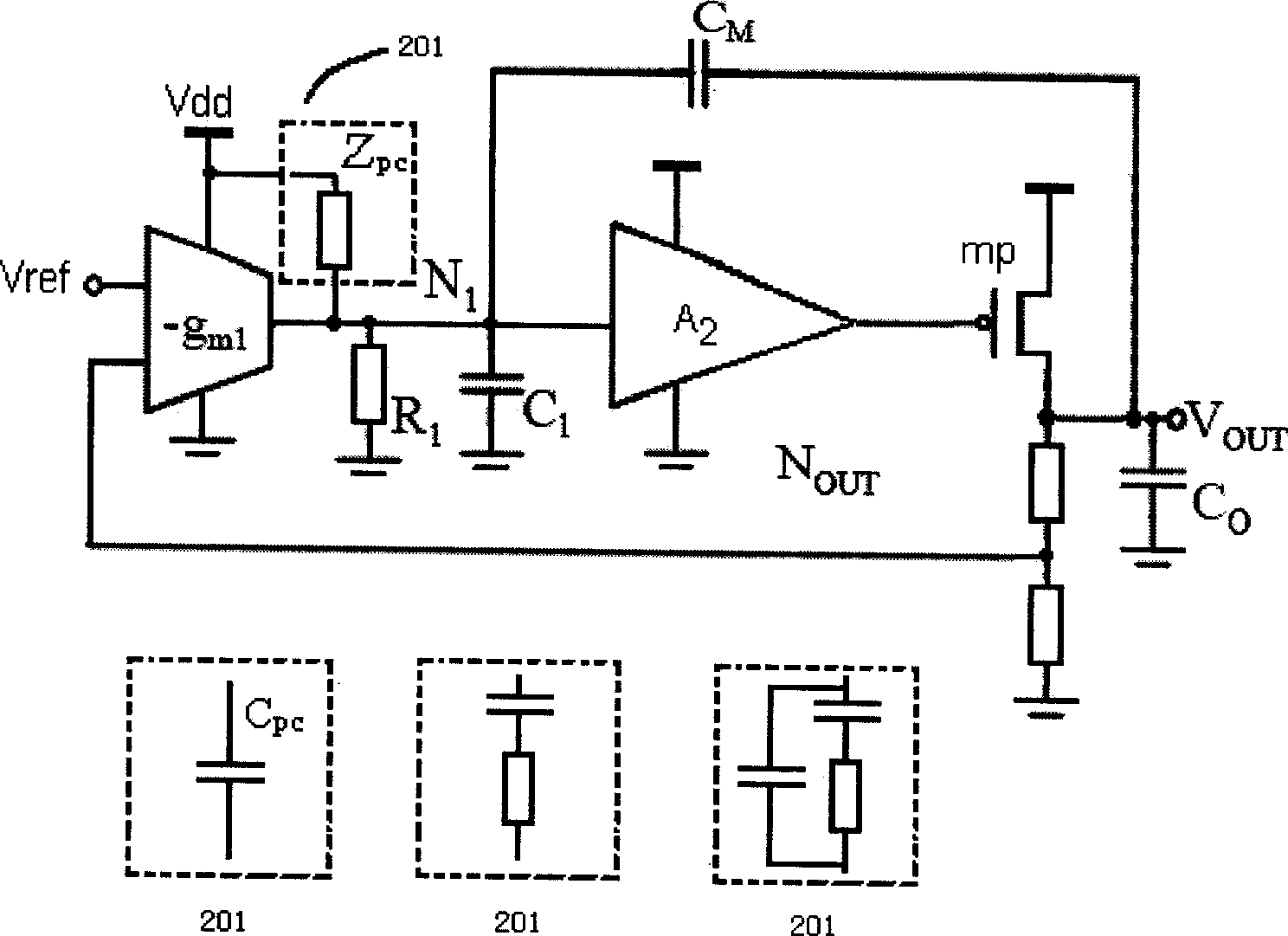
[0015] When the LDO does not use the Miller capacitor, the zero point of the PSRR curve of the LDO is given by (1).

[0016] Zero 1 = 1 R 1 C 1 - - - ( 1 )

[0017] After adopting the Miller compensation, the zero point of the PSRR curve of LDO is given by (2) test.

[0018] Zero M = 1 R 1 C M - - - ( 2 )

[0019] Among them, R 1 , C 1 and C M are the output resistance of the first-stage amplifier, that is, the error amplifier, the equivalent output capaci...


PUM


Abstract

A low dropout linear regulator with high power supply rejection ratio is characterized in that a compensation network (201) with transmission function being Zpc and the ability of reducing equivalent output capacitance of N1 node is arranged between a power supply Vdd and the output end of an error amplifier. With the adoption of the low dropout linear regulator, near-zero points on PSRR curve are effectively pushed away, the stabilization of the LOD can be kept when the PSRR property at high frequency is improved, and the problem that PSRR main zero points are too small, caused by the miller effect, is solved.

Description

technical field [0001] The present invention relates to low dropout voltage linear regulator (Low DropOut Voltage Linear Regulator, abbreviated as LDO) technology, in particular to a low dropout linear regulator (LDO) with high power supply rejection ratio (High PSRR). Background technique [0002] LDOs are widely used in wireless devices to provide a stable, low-noise output voltage for the entire system. The power supply rejection ratio (Power Supply Rejection Ratio, abbreviated as "PSRR") of the LDO is used to measure the ability of the LDO to suppress power supply noise. Miller compensation (miller compensation) is a typical frequency compensation technology, mainly by separating the primary and secondary poles, so that only the main pole is included in the unity gain bandwidth to obtain a higher phase margin. like figure 1 The shown Miller compensation (miller compensation) is widely used in the frequency compensation of LDO, and its basic principle is: through the Mi...

Claims


Application Information

Patent Timeline
IPC IPC(8): G05F1/46
Inventor 谭润钦方磊谷文浩
Owner FREMONT MICRO DEVICES SHENZHEN LTD
Why Eureka
Try Eureka