
Optical testing device

A technology of optical testing and sample light, applied in the optical field, can solve the problems of too small sample 5, reduced data accuracy, low light source intensity, etc., and achieve the effect of not reducing the light source intensity, reducing the size, and accurately focusing

Inactive Publication Date: 2018-09-21
SHENZHEN CHINA STAR OPTOELECTRONICS TECH CO LTD
View PDF5 Cites 0 Cited by
  • Summary
  • Abstract
  • Description
  • Claims
  • Application Information

AI Technical Summary

Problems solved by technology

[0008] Although the above two methods can solve the problem that the sample 5 is too small, there are some disadvantages, and no matter whether the light shield 8 is added at the light source or the light outlet, the intensity of the light source will be reduced. samples with low efficiency), the light source intensity is low, and the data accuracy will be reduced

Method used


Image

  • Optical testing device
  • Optical testing device
  • Optical testing device

Examples


Embodiment Construction

[0033] Reference will now be made in detail to embodiments of the present invention, examples of which are illustrated in the accompanying drawings, wherein like numerals refer to like parts throughout. The embodiments are described below in order to explain the present invention by referring to the figures.

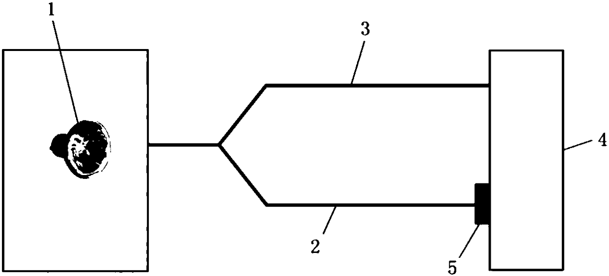
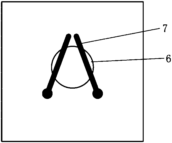
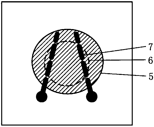
[0034] refer to figure 1 and Figure 4 , in the prior art, when testing the optical parameters characterizing the sample with a UV spectrophotometer, if the sample 5 is smaller than the light-transmitting hole 6 and cannot completely block the light-transmitting hole 6, then between the sample 5 and the light-transmitting hole 6 A blank area 61 capable of light transmission will be formed (such as Figure 4 shown). Existing solutions are based on the idea of ​​shading, for example, refer to Figure 5 and Figure 6 , set the mask 8 at the light source 1 or at the light outlet of the sample optical path 2 and the reference optical path 3, but this method will reduce t...


PUM


Abstract

The invention provides an optical test device. The optical testing device comprises a sample light path and a light-transmitting hole positioned on the sample light path and used for placing a sample,wherein the sample is smaller than the light-transmitting hole, and the optical testing device further comprises a light-collecting mechanism arranged on the sample light path, so that the light on the sample light path is converged on the sample through the light-collecting mechanism. According to the optical testing device, the size of the light spot is reduced by collecting the light on the sample light path, so that the sample can be accurately focused, and the intensity of the light source is not reduced while the problem that the sample is too small is solved.

Description

technical field [0001] The invention relates to the field of optical technology, more specifically, to an optical test device. Background technique [0002] In the field of material analysis testing and semi-finished product analysis, optical performance is an essential item, and UV-visible spectrophotometers are often used to characterize optical parameters in the ultraviolet and visible regions. figure 1 A simplified optical path of a UV-Vis spectrophotometer according to the prior art is shown. Such as figure 1 As shown, ultraviolet light or visible light is emitted by a light source 1 and divided into a sample light path 2 and a reference light path 3 . Among them, the reference optical path 3 enters the detector 4, and the sample optical path 2 passes through the sample 5 to reach the detector 4. Optical information such as the transmittance of the sample 5 can be obtained by comparing the light intensity of the reference optical path 3. Performance improvement or pr...

Claims


Application Information

Patent Timeline
Patent Type & Authority Applications(China)
IPC IPC(8): G01N21/01
CPCG01N21/01
Inventor 张维维
Owner SHENZHEN CHINA STAR OPTOELECTRONICS TECH CO LTD
Learn More