
Method for indicating neighbour zone information and network side equipment

A technology for network-side equipment and neighbor information. It is used in wireless communication, advanced technology, sustainable buildings, etc. It can solve problems such as excessive buffering, increased terminal energy consumption, and reduced system efficiency, reducing load, reducing energy consumption, and reducing energy consumption. The effect of preventing excessive caching

Active Publication Date: 2009-06-24
SHANGHAI HUAWEI TECH CO LTD
View PDF0 Cites 11 Cited by
  • Summary
  • Abstract
  • Description
  • Claims
  • Application Information

AI Technical Summary

Problems solved by technology

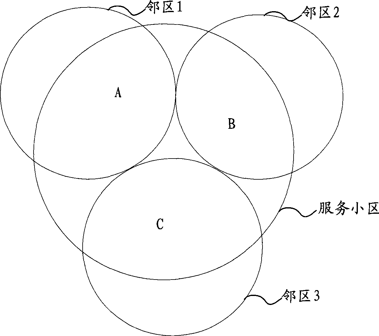
For example, if a terminal in area A of the serving cell receives the neighboring cell list information of the serving cell, the terminal will measure and evaluate all three neighboring cells according to the neighboring cell list information, but the actual effective neighboring cells only have the coverage area Neighbor cell 1 of A, although neighbor cell 2 and neighbor cell 3 do not cover the terminal in area A, the terminal still needs to perform invalid measurement and evaluation
Therefore, in the solution provided by the prior art, for the terminal, since the effective coverage of the neighboring cells of the current serving cell cannot be obtained, unnecessary idle periods will be scheduled to perform measurement of invalid neighboring cells, resulting in excessive user data Caching reduces system efficiency and business service quality, further complicating resource scheduling and network; at the same time, the measurement of invalid neighbors also increases terminal energy consumption

Method used


Image

  • Method for indicating neighbour zone information and network side equipment
  • Method for indicating neighbour zone information and network side equipment
  • Method for indicating neighbour zone information and network side equipment

Examples


no. 1 approach

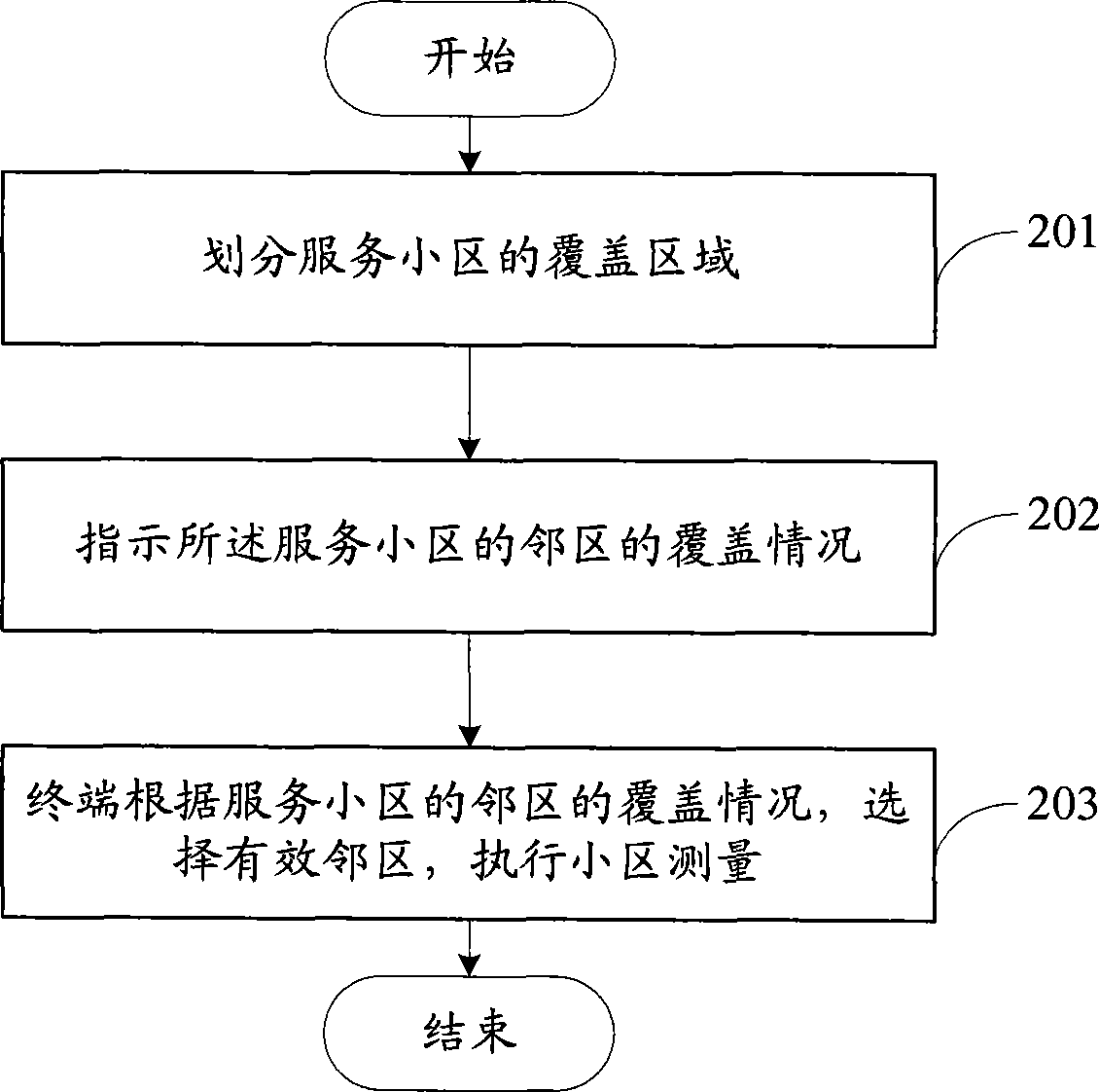
[0020] refer to figure 2 , to introduce the first embodiment of the present invention, about a method for indicating neighbor cell information. The method includes:

[0021] Step 201: dividing the coverage area of ​​the serving cell;

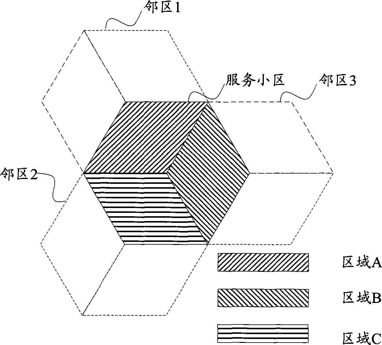
[0022] In this embodiment, according to the requirements of network planning, the coverage area of ​​the serving cell can be divided into at least two areas, such as image 3 As shown in , it is a schematic diagram of dividing the coverage area of ​​the serving cell into three partitions. In a network system, one or more partition modes may be included. For the divided partition mode, the terminal may be notified in an explicit or implicit manner. The explicit method means that the network system explicitly informs the terminal of the coverage area division mode of the service cell through messages; The preset method informs the terminal.

[0023] Step 202: Indicate the coverage of the neighboring cells of the serving cell.

[0024] The ...


PUM


Abstract

The invention discloses an adjacent-area information indicating method, which comprises the following steps: dividing the overlay area of a service subdistrict; and indicating the overlay condition of the divided area for the adjacent area of the service subdistrict. At the same time, the invention also discloses another adjacent-area information indicating method, which comprises the following steps: adding the indicating information of a same frequency subdistrict into the subdistrict list of the different frequency subdistrict; and transmitting adjacent information including the indicating information. Through the technical proposal provided by the invention, the adjacent area information of the valid service subdistrict can be indicated, so as to lead the terminal in the service subdistrict to only select the adjacent area overlaying the terminal to for subdistrict measurement according to the valid overlaying condition of the adjacent area of the service subdistrict, thus reducing the load to the adjacent area measurement, ensuring the system efficiency, lowering the complexity of the dispatch and network, and also leading the terminal to reduce the energy consumption. The invention also discloses a network side device.

Description

technical field [0001] The present invention relates to the technical field of wireless communication, in particular to a technique for indicating neighbor cell information. Background technique [0002] With the development of communication technology, multiple wireless access systems coexist in the wireless communication network, such as GSM (Global System of Mobile Communication, Global System for Mobile Communication), WCDMA system, TD-SCDMA (Time Division-Synchronous Code Multiple Access (time division synchronous code division multiple access) system, LTE (Long Term Evolution, long-term evolution) system and WLAN (Wireless Local Area Network, wireless local area network) system, etc., in the same wireless access system, in order to expand the system capacity, Different cells may also use different carrier frequencies. Therefore, during the process of cell selection, cell reselection, and service handover, the user terminal needs to be in the same frequency cell (intra...

Claims


Application Information

Patent Timeline
Patent Type & Authority Applications(China)
IPC IPC(8): H04W24/10
CPCY02B60/50Y02D30/70
Inventor 马小飞黄颖华
Owner SHANGHAI HUAWEI TECH CO LTD
Learn More