
Method and apparatus for auto-focussing infinity corrected microscopes

An automatic focus and microscope technology, applied in the field of optical microscopes, can solve problems such as performance limitations of efficient AF equipment

Inactive Publication Date: 2009-06-24
WDI WISE DEVICE
View PDF0 Cites 14 Cited by
  • Summary
  • Abstract
  • Description
  • Claims
  • Application Information

AI Technical Summary

Problems solved by technology

The efficiency of both AOI techniques is severely limited by the performance of currently available AF equipment

Method used


Image

  • Method and apparatus for auto-focussing infinity corrected microscopes
  • Method and apparatus for auto-focussing infinity corrected microscopes
  • Method and apparatus for auto-focussing infinity corrected microscopes

Examples


Embodiment Construction

[0028] In general, the present invention provides a method and system for autofocusing an infinity corrected microscope. The invention is particularly useful in thin film transistor (TFT) array inspection, photolithographic mask inspection, silicon wafer inspection, and micromachining and coordinate measuring machines (CMM).

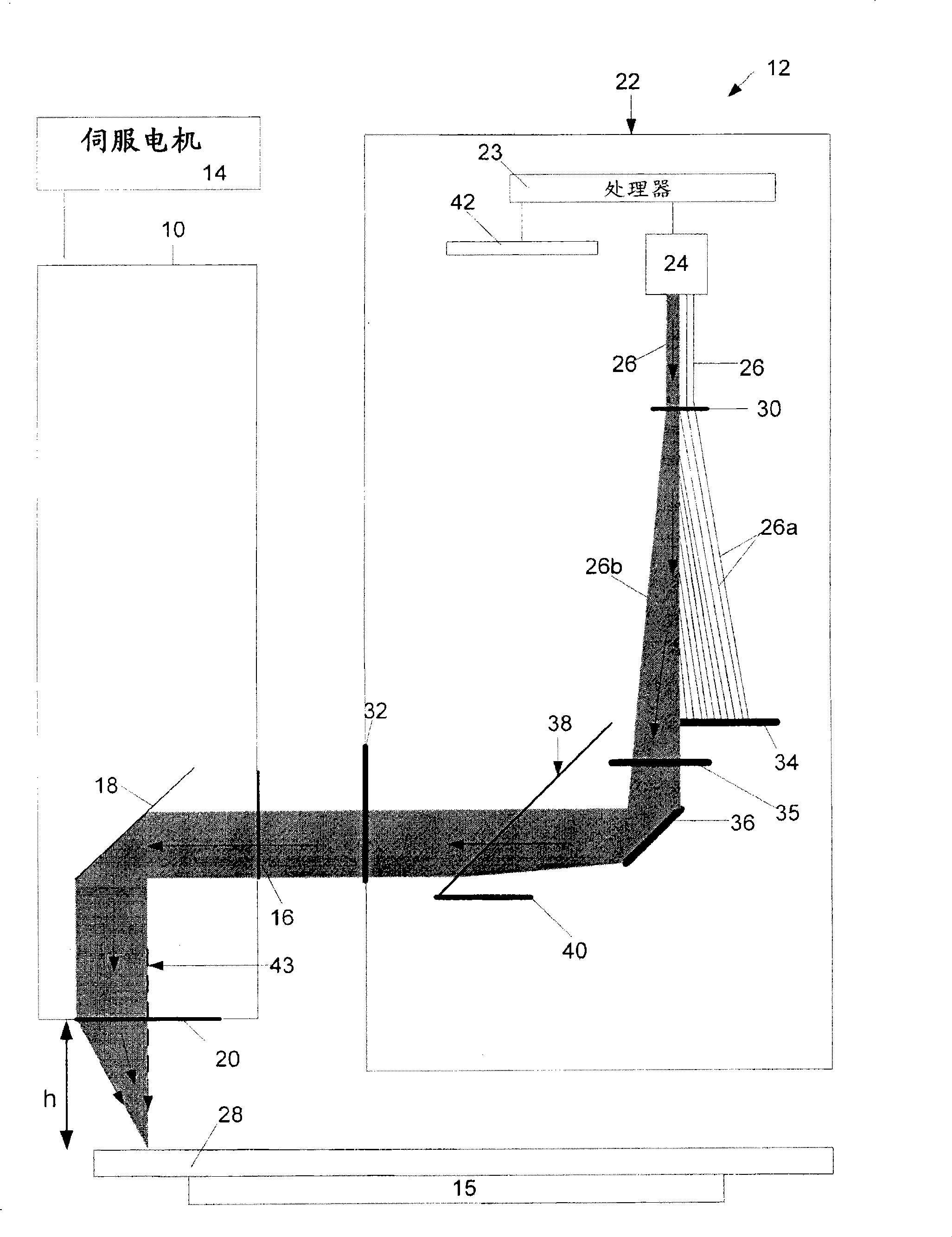
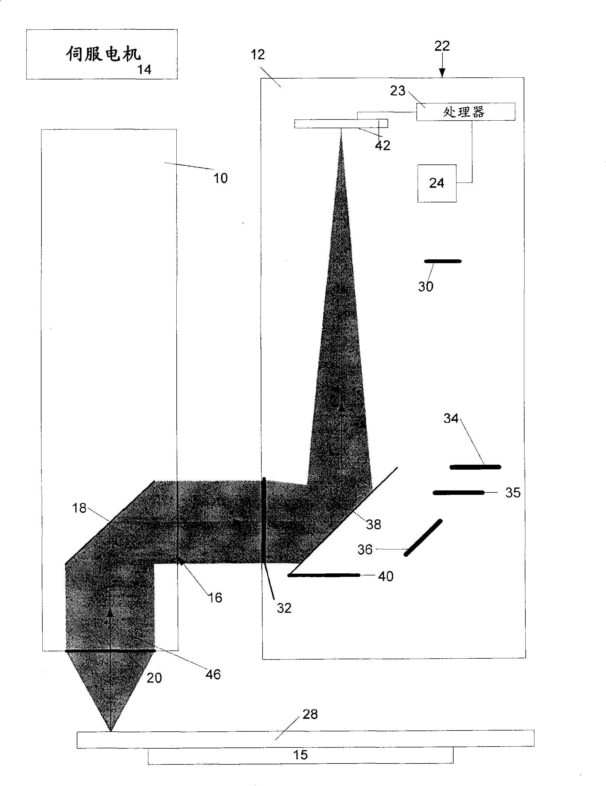
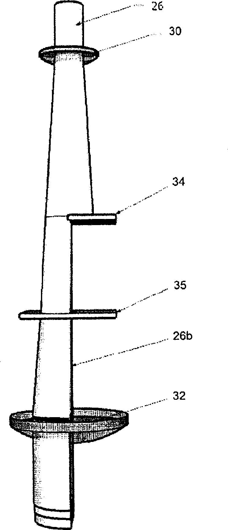
[0029] go to Figures 1a to 1d , a schematic diagram of an embodiment of an autofocus device for an infinity-corrected microscope is shown. Figure 1a For a schematic view of the device providing the output beam, Figure 1b is a schematic view of the reflected beam after the output beam has been reflected off the sample, and Figure 1c with 1d is the 3D view of the output beam.

[0030] exist Figure 1a In , an infinity-corrected microscope 10 is shown having an autofocus device 12, such as a detector. Although shown discretely, it is understood that device 12 may be integrated within microscope 10 , or mounted within, and typically an accessory to, ...


PUM


Abstract

The invention is directed at a method and apparatus for auto-focussing an infinity corrected microscope. Light beams are directed and then converged towards a specimen of interest and at least one image is formed from the reflected light. The image, or images, are then reviewed and calibration measurements are retrieved from the image. These calibration measurement are then used to determine focusing measurements which are used to auto-focus the microscope.

Description

[0001] Cross References to Related Applications [0002] This application claims the benefit of priority to US Provisional Patent Application No. 60 / 804,305, filed June 9, 2006, which is hereby incorporated by reference. technical field [0003] The present invention relates generally to optical microscopy. More specifically, the present invention relates to a method and apparatus for autofocusing an infinity corrected microscope. Background technique [0004] In the field of optical microscopy, in order to obtain meaningful images, the microscope must be focused on the object or sample being inspected. During the time the microscope is focused on the sample, the microscope cannot be used. To this end, considerable efforts have been made to minimize the focusing time and to automate the process. This is commonly referred to as autofocus (AF). [0005] AF has become more common in the industry due to the introduction of automated optical inspection (AOI) of media. AOI in...

Claims


Application Information

Patent Timeline
Patent Type & Authority Applications(China)
IPC IPC(8): G02B7/28G02B7/36G02B21/00
CPCG02B21/244G02B7/38
Inventor 亚当·韦斯亚历山大·奥博特那安德鲁·拉辛斯基
Owner WDI WISE DEVICE
Learn More