
Heating element

A heating element and heating plate technology, which is applied in printing and other directions, can solve the problems of simultaneous driving of heating elements, adding heating elements, printer power supply can not be loaded, etc.

Inactive Publication Date: 2009-07-01
MICROJET TECH
View PDF0 Cites 0 Cited by
  • Summary
  • Abstract
  • Description
  • Claims
  • Application Information

AI Technical Summary

Problems solved by technology

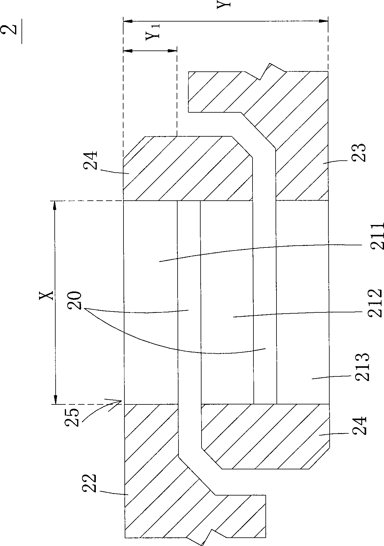
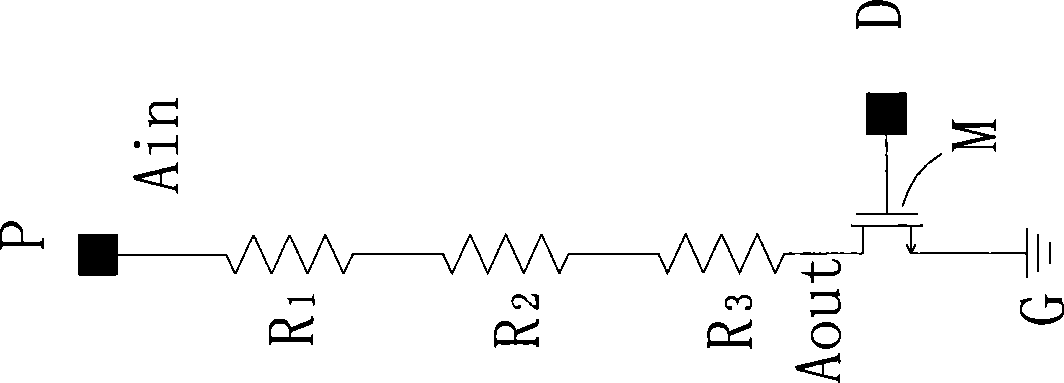
[0007] The main purpose of this case is to provide a heating element, which electrically connects a plurality of separate heating plates arranged side by side in series through a conductive layer, and the heating plates at opposite ends are respectively electrically connected to the input end and the output end, This increases the resistance value of the heating element to avoid the known inconvenience of increasing the resistance value by changing the material or volume ratio of the heating element, and solves the problem that the printer power supply cannot be driven by too many heating elements at the same time, which affects the inkjet frequency. question

Method used


Image

  • Heating element
  • Heating element
  • Heating element

Examples


Embodiment Construction

[0031] Some typical embodiments embodying the features and advantages of the present application will be described in detail in the description in the following paragraphs. It should be understood that the present case can have various changes in different aspects without departing from the scope of the present case, and the descriptions and diagrams therein are used for illustration in nature rather than limiting the present case.

[0032] The heating element in this case is mainly applied to the structure of the inkjet head of the printing device, such as the structure of the inkjet head of the inkjet printer (not shown), but not limited thereto. Please refer to FIG. 2( a ), which is a schematic diagram of the heating element of the first preferred embodiment of the present case. As shown in the figure, the heating element 2 mainly includes a plurality of heating plates 211-213, an input terminal 22, an output terminal 23, and a conductive layer 24 connecting two adjacent he...


PUM


Abstract

The invention relates to a heating element, which is applicable to an inkjet head structure. The heating element comprises a plurality of heating plates which are arranged separately and parallelly, and electrically connected in series mutually through conductive layers, so as to form ink jetting areas. The heating plates opposite to both terminals are electrically connected with an input terminal and an output terminal respectively.

Description

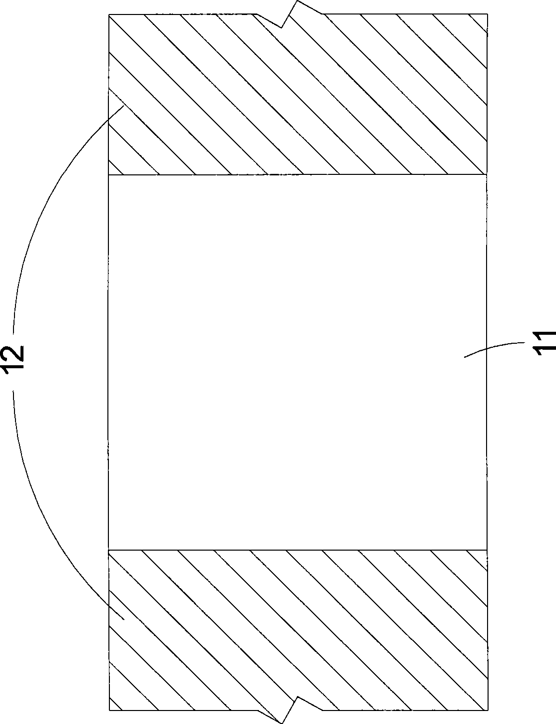
technical field [0001] The invention relates to a heating element, especially a heating element applied to an inkjet printer. Background technique [0002] Existing inkjet printers generally use a thermal bubble inkjet head to perform inkjet action, and the thermal bubble inkjet head is equipped with a heating plate to heat the ink by using the heating plate to vaporize the ink and eject it onto the inkjet medium. [0003] see figure 1 , which is a schematic diagram of a heating element of a known thermal bubble inkjet head. As shown in the figure, the heating element 1 has a single heating plate 11, the heating plate 11 is composed of a resistive layer, and two opposite sides are connected to the conductive layer 12, so that the voltage is input from one of the conductive layers 12 to heat the resistive layer, so that the heating The plate 11 heats up to vaporize ink (not shown) to eject ink. In order to obtain the best temperature distribution effect and generate high-e...

Claims


Application Information

Patent Timeline
IPC IPC(8): B41J2/14B41J2/05
Inventor 余荣侯戴贤忠
Owner MICROJET TECH
Learn More