
Middle arranged tension device

A tension device and tension roller technology, applied in other manufacturing equipment/tools, textiles and papermaking, warping machines, etc., can solve the problems of difficult control, uneven single yarn tension, large fluctuations in sliver and sheet tension, etc. To achieve the effect of meeting the tension requirements

Inactive Publication Date: 2009-07-01
射阳县中意纺织机械制造有限公司
View PDF5 Cites 3 Cited by
  • Summary
  • Abstract
  • Description
  • Claims
  • Application Information

AI Technical Summary

Problems solved by technology

Due to the change of the diameter of the bobbin during the warping process, the difference in the position, the density difference of the bobbin, the difference in the warping speed and the adjustment of the tensioner, etc., the tension of the single yarn in the sliver and sheet yarn is not uniform. The tension of slivers and sheet yarns fluctuates greatly, which is difficult to control, thus affecting the quality of warp yarns

Method used

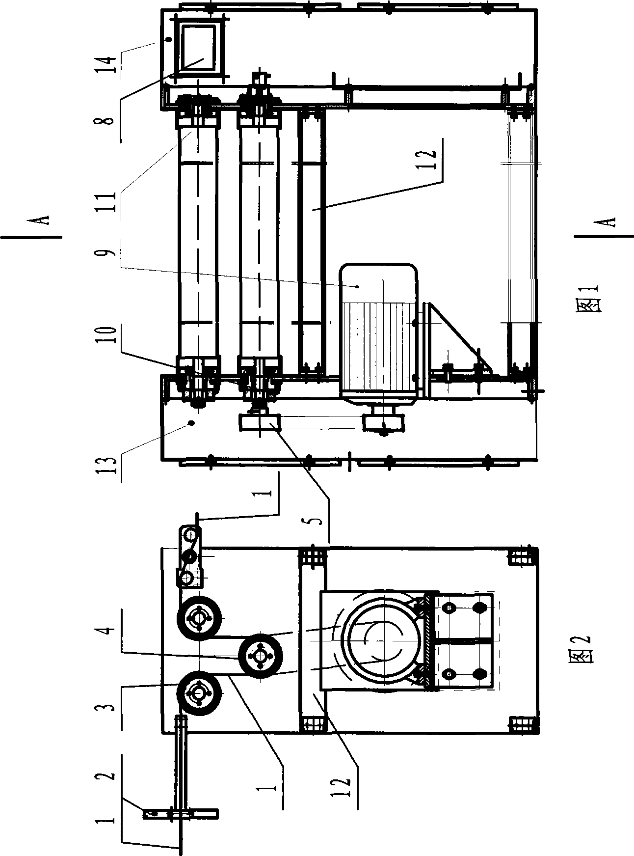
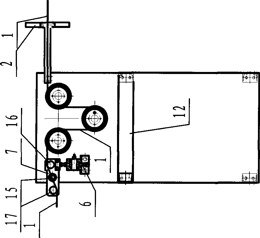
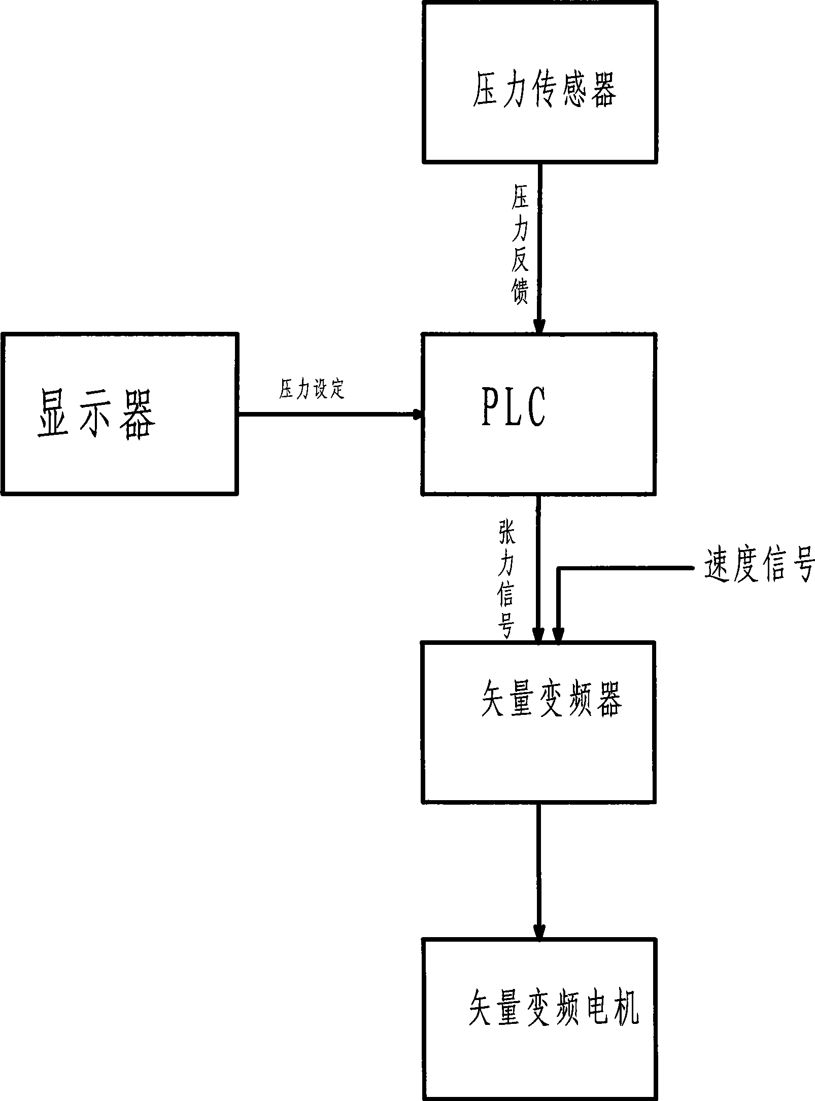

Image

  • Middle arranged tension device
  • Middle arranged tension device
  • Middle arranged tension device

Examples


Embodiment Construction

[0014] Describe the present invention in detail below in conjunction with accompanying drawing:

[0015] As shown in Figure 1-3, this tension device comprises motor 9, left box body 13, right box body 14, support beam 12, yarn 1, steel reed 2, guide roller 3, tension roller 4; Steel reed 2 The two ends of the two ends are respectively fixed on the inner side of the yarn 1 input port of the left box body 13 and the right box body 14 wallboards by their supporting arms; On the wallboard of the right box body 14, the left box body 13 and the right box body 14 are connected by brace beams 12 to form a whole. Motor 9 axles are connected with the rotating shaft of tension roller 4 one ends by synchronous pulley 5 and synchronous belt. Electromagnetic brakes 10 are respectively provided at one end of the two guide rollers 3 and the tension roller 4; a rotary encoder 11 is also arranged at the other end of the tension roller 4.

[0016] Motor 9 is a vector frequency conversion motor...


PUM


Abstract

The invention relates to a center disposed tension device of a warping machine, which is characterized in that: the motor is a vector frequency control motor electrically connected with an automatic control device for controlling rotation speed of let-off tension roller; the tension roller is disposed on bottom portion between two yarn guide rollers; pins are disposed on inner surface of the yarn outlet on the wall of the left box body and the right box body respectively, two connection plates are movably engaged with pins through a central hole, both ends of the tension rod (a) and the tension rod (b) are attached on both sides of the pin engaged with central holes of two connection plates; a pressure sensor contact is disposed on inner surface wall of left or right box body, which is in contact with the bottom side of the tension rod (a) axle neck permanently. The center disposed tension device makes the yarn form a wrapping angle through the yarn guidance roller, the tension roller, and the yarn guidance roller, makes the yarn and the yarn guidance roller generates adhesion, implements closed-loop control to the yarn tension through on-line detection of the pressure sensor, and satisfies needed tension requirements in the warping process.

Description

Technical field: [0001] The invention relates to a textile machine, in particular to a tension device installed in a warping machine. Background technique: [0002] At present, there is no central tension device between the creel and the split reed of the warping machine on the market, and the yarn is directly from the creel to the split reed. Due to the change of the diameter of the bobbin during the warping process, the difference in the position, the density difference of the bobbin, the difference in the warping speed and the adjustment of the tensioner, etc., the tension of the single yarn in the sliver and sheet yarn is not uniform. The tension of slivers and sheet yarns fluctuates greatly and is difficult to control, thus affecting the quality of warp yarns. Contents of the invention [0003] The purpose of the present invention is to add a central tension device between the creel and the reed of the warping machine, and reduce the difference in single yarn tension...

Claims


Application Information

Patent Timeline
Patent Type & Authority Applications(China)
IPC IPC(8): D02H13/22D02H3/00
Inventor 周兆兵
Owner 射阳县中意纺织机械制造有限公司
Learn More