
Method and device for detecting movement track of automotive tire

A technology of automobile tires and motion tracks, which is applied in the field of machinery, can solve the problems of complex structure, inconvenient testing, and inaccurate reflection of wheel alignment detection devices, and achieve the effect of convenient operation and simple structure

Inactive Publication Date: 2009-07-01
SHANGHAI TONGYUN AUTOMOBILE TECH
View PDF0 Cites 8 Cited by
  • Summary
  • Abstract
  • Description
  • Claims
  • Application Information

AI Technical Summary

Problems solved by technology

[0003] The object of the present invention is to provide a method for detecting the motion track of automobile tires. The detection system for the motion track of automobile tires needs to solve the problem that the wheel alignment detection device in the prior art cannot accurately reflect the deviation when the wheels touch the ground, the structure is complex and huge, and the test inconvenient technical problem

Method used


Image

  • Method and device for detecting movement track of automotive tire
  • Method and device for detecting movement track of automotive tire
  • Method and device for detecting movement track of automotive tire

Examples


Embodiment Construction

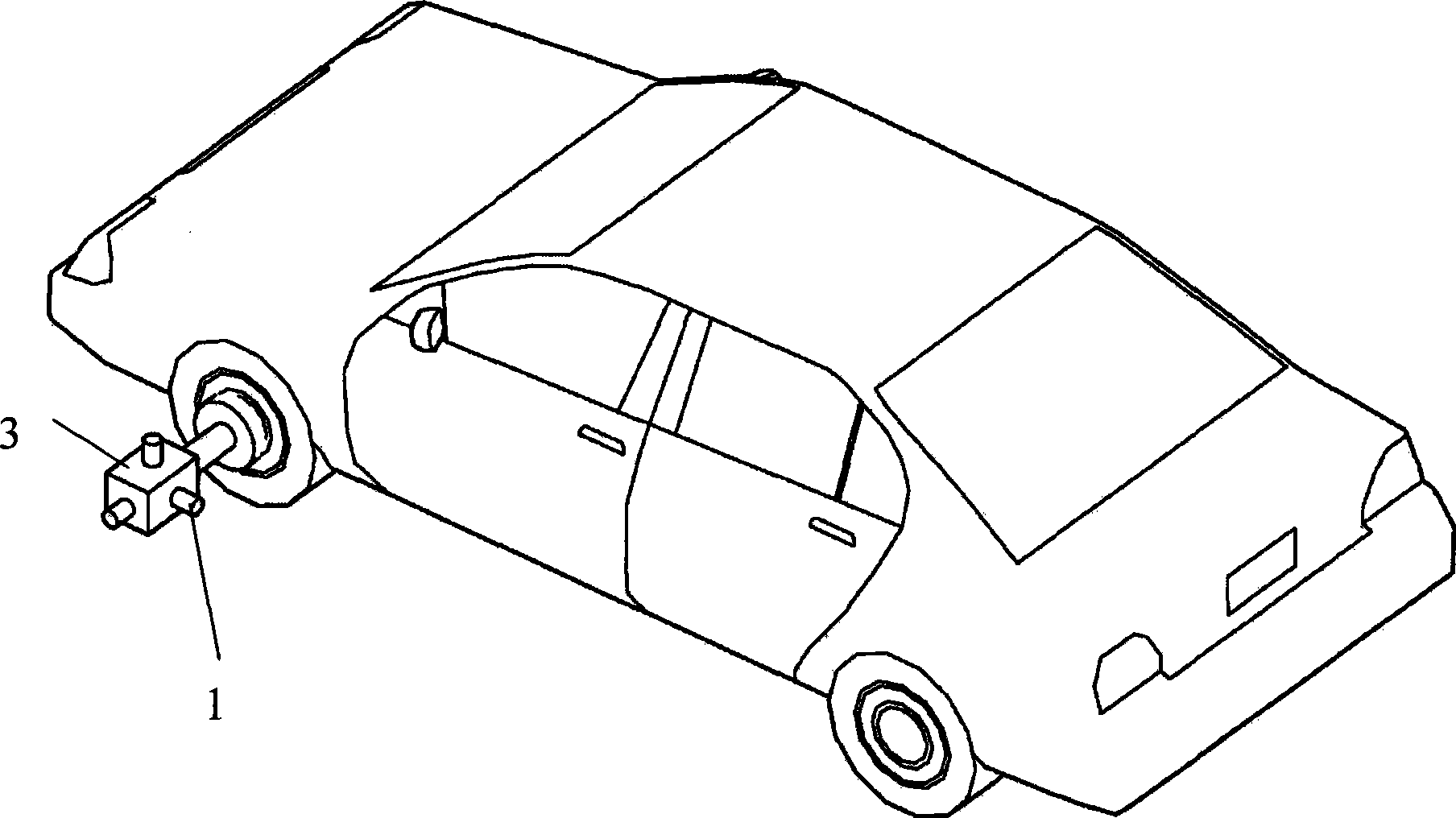
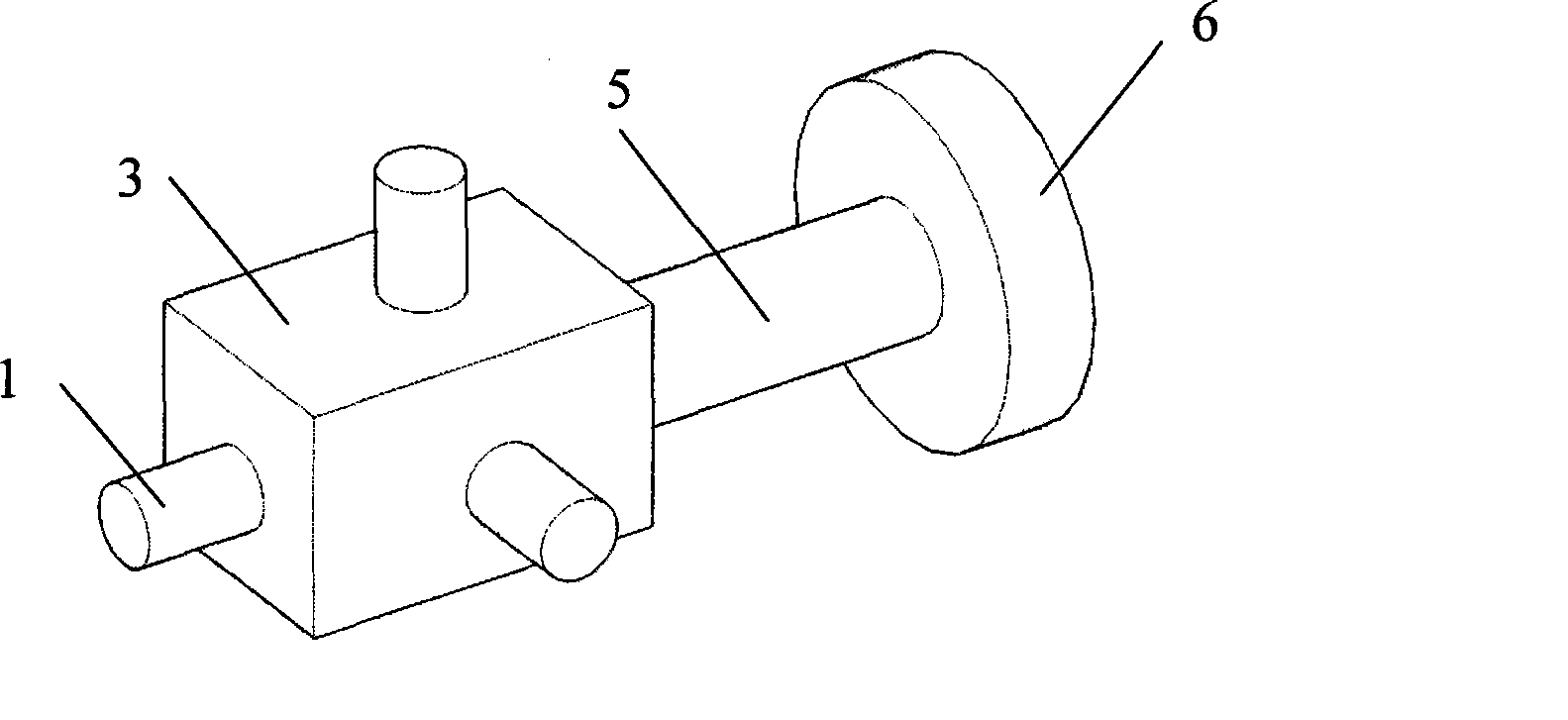
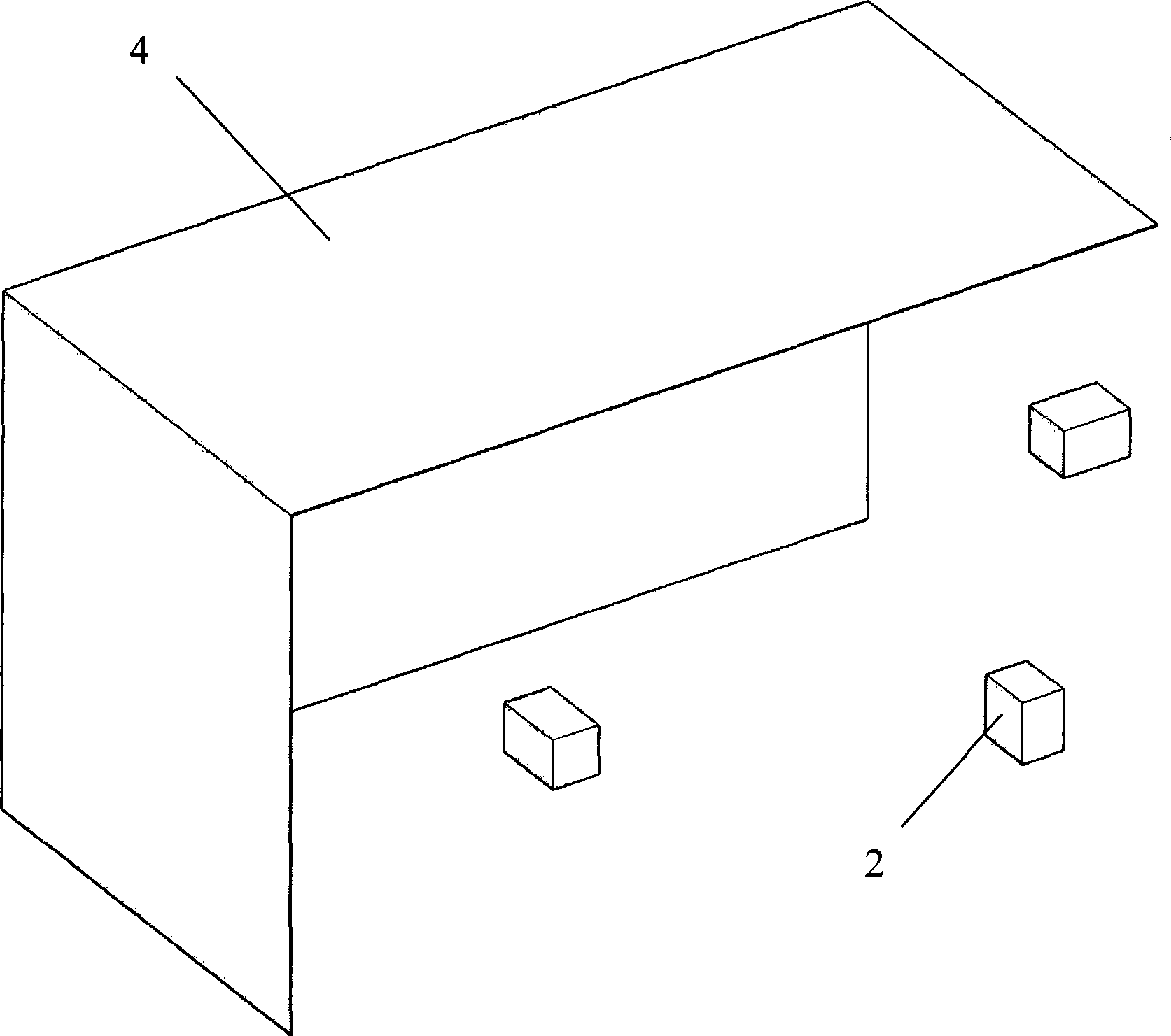
[0015] like figure 1 , figure 2 and image 3 As shown in the figure, the method for detecting the motion track of an automobile tire of the present invention includes a process of recording the motion track of the automobile tire, wherein, in the process of recording the motion track of the automobile tire, three laser indicators are fixedly connected on the outer end face of the automobile tire device 1, adjust the laser projection directions of the three laser pointers 1 to be perpendicular to each other and intersect, and use the three laser pointers 1 to project laser beams on three mutually perpendicular projection screens to push the car forward or Back up, the camera 2 is used to record the positions of the laser beams on the three mutually perpendicular projection screens. Finally, mathematical methods are used to calculate the caster angle of the wheel, the inclination angle of the kingpin, Front camber and front toe.

[0016] Further, after the tire of the car to...


PUM


Abstract

The invention relates to an automobile tire motion track test method, comprising fixedly connecting three laser indicators vertical and crossed with each other to the outer end face of a tire; projecting laser beams to three projection screens vertical to each other; driving the vehicle forward; using cameras to record the positions of the laser beams on the projection screens vertical to each other; according to the positions of the three laser beams on the projection screens, calculating main pin trim angle, main pin leaning angle, front wheel lateral obliquity angle and front wheel front beam. A device realizing the method is composed of a connecting base, three cameras and three projection plates, wherein the three projection plates are respectively arranged on the laser projection directions of the three laser indicators and are vertical and crossed with each other, the three cameras are respectively arranged at the front of the projection plates. The invention utilizes three laser indictors and three projection plates to display the motion state of automobile tires in space rectangular coordinates, to accurately reflect the grounding deviation of tires, having simple structure and operation.

Description

Technical field: [0001] The invention relates to the field of machinery, in particular to vehicles, and in particular to a method and device for detecting the motion trajectory of automobile tires. Background technique: [0002] After the car has been used for a period of time, the positioning values ​​of the caster angle of the kingpin, the inclination angle of the kingpin, the camber angle of the front wheel and the toe-in of the front wheel may deviate, resulting in heavy steering, deviation of the car, and abnormal tire wear. Affect vehicle performance and safety. In the prior art, the device for detecting wheel alignment needs to be tested after the vehicle is lifted. However, after the vehicle is lifted, the wheels are not subject to the pressure of the vehicle body, and cannot accurately reflect the deviation of the wheels when they land on the ground. At the same time, the structure of the detection device in the prior art is complex. Bulky and inconvenient to test....

Claims


Application Information

Patent Timeline
Patent Type & Authority Applications(China)
IPC IPC(8): G01B21/00G01B21/22G01B11/00G01B11/26G01M17/007
Inventor 蒋妙范宋建勋
Owner SHANGHAI TONGYUN AUTOMOBILE TECH
Learn More