
Apparatus for enhancing digital image luminance contrast

A technology of brightness and contrast enhancement device, which is applied in the directions of image communication, TV, color TV components, etc., can solve the problems of not using curve mapping, consuming large storage space, inflexible and accurate, etc., to achieve convenient and flexible adjustment and adjustment effect. Good, improve the effect of image contrast

Active Publication Date: 2009-07-01
ARKMICRO TECH
View PDF2 Cites 16 Cited by
  • Summary
  • Abstract
  • Description
  • Claims
  • Application Information

AI Technical Summary

Problems solved by technology

[0006] In the U.S. patent US6826310 applied for on May 20, 2003, an automatic contrast enhancement method is proposed, which uses the histogram to count the brightness characteristics of the image, and selects an S-curve with a certain radian as the contrast adjustment method of the brightness mapping curve. The method selects different curves for different brightness characteristics, and the adjustment of the image is more in line with the actual situation. However, since the realization of the curve is realized through a lookup table, accessing the curve of the entire brightness range not only consumes a large amount of storage space, but also when a When the luminance characteristics of different luminance areas of an image are different, only one S-curve is not flexible enough.
[0007] In the U.S. patent US6463173 filed on October 30, 1995, a contrast enhancement system and method based on image histogram was proposed, which divided the histogram of the image into multiple segments, and stretched the histogram of each segment to adjust the image's contrast. Contrast, this method can be adjusted separately according to different brightness feature segments of the image, and the effect is better, but it does not use the method of curve mapping, and directly performs histogram equalization, which is not suitable for the implementation of hardware code, and is very complicated

Method used


Image

  • Apparatus for enhancing digital image luminance contrast
  • Apparatus for enhancing digital image luminance contrast
  • Apparatus for enhancing digital image luminance contrast

Examples


specific Embodiment 1

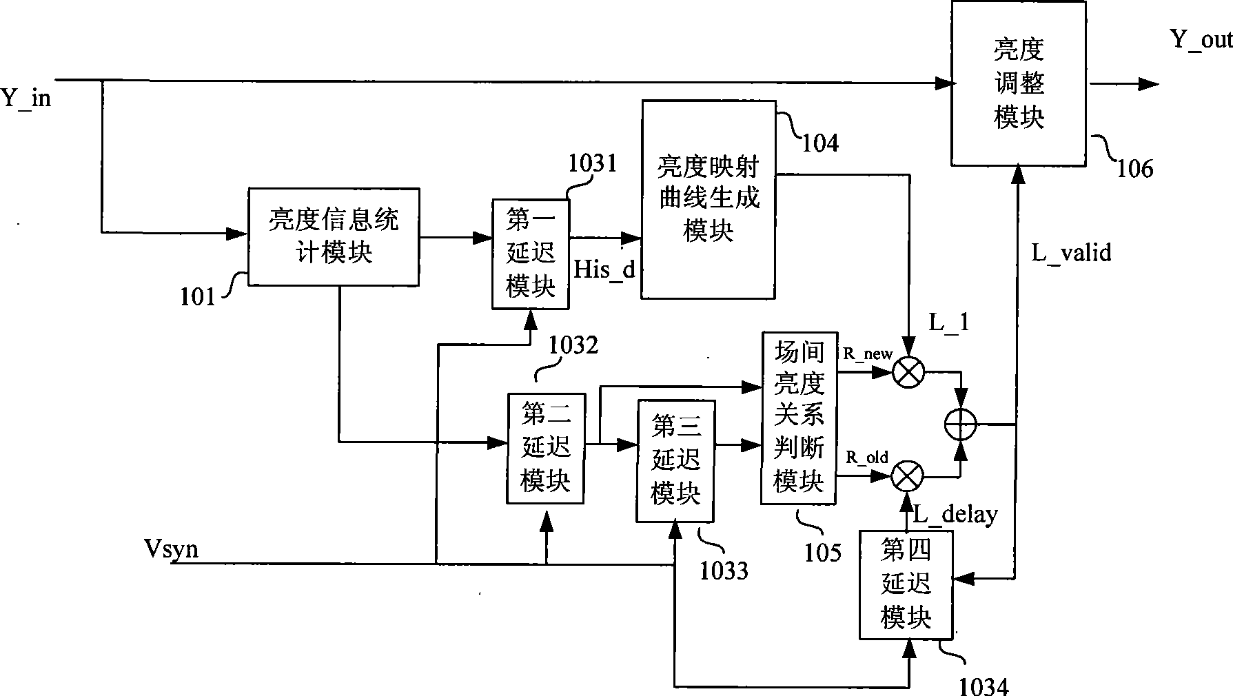
[0043] figure 1 It is a block diagram of the overall structure of this embodiment, including a brightness information statistics module 101, a first delay module 1031, a second delay module 1032, a third delay module 1033, a fourth delay module 1034, a brightness mapping curve generation module 104, and an inter-field brightness The relationship judgment module 105 and the brightness adjustment module 106, wherein, the four delay modules 1031 to 1034 are the same modules.

[0044] In this specific embodiment, the brightness signal Y_in is input to the brightness information statistical module 101 to obtain the histogram statistical information and brightness average value of the current field; the delayed histogram information His_d is obtained after the histogram statistical information passes through the first delay module 1031 and is input to The brightness mapping curve generation module 104 initially generates the brightness mapping curve L_1 of the current field. At the...

specific Embodiment ( 2

[0120] The overall structural block diagram of this embodiment is as attached Figure 10 As shown, the same as the overall structural block diagram of the specific embodiment 1, it includes a brightness information statistics module 101, a first delay module 1031, a second delay module 1032, a third delay module 1033, a fourth delay module 1034, a brightness The mapping curve generation module 104, the inter-field brightness relationship judgment module 105, and the brightness adjustment module 106; the difference is that the approximate saturation calculation module 102 and the fifth delay module 1035 are also included in this embodiment.

[0121] Due to the addition of the approximate saturation calculation module 102, the input data in this embodiment is the brightness signal Y_in, and the color difference signals Cb_in and Cr_in, wherein the color difference signals Cb_in and Cr_in are input into the approximate saturation calculation module 102 to obtain an average approxi...


PUM


Abstract

The invention provides a digital image brightness contrast enhancement device. The device comprises a brightness information statistics module, a first delay module, a second delay module, a third delay module, a fourth delay module, a brightness projected curve generation module, an interfield brightness relationship judgment module and a brightness control module. The image is divided into three parts for adjustment according to the brightness, and can be adjusted according to the brightness distribution characteristics of different brightness areas, and not only the contrast of the entire image is well promoted, but also the distortion caused during the process of adjusting the position where the adjustment is not required is avoided; the realizability of the hardware is considered at all time during the realization, the complexity is reduced, and the storage space is saved, therefore, the invention is convenient for being integrated to the chip; and in addition, the device further comprises an approximate saturation computation module and a fifth delay module, and the adjustment effect of the contrast control device to the colorful image is better with the consideration of image saturation.

Description

technical field [0001] The invention relates to a digital video signal processing device, in particular to a digital video signal enhancement processing device. Background technique [0002] In today's information age, people have higher and higher requirements for the display of video images. In many current digital video systems, in addition to making great improvements in the signal-to-noise ratio and resolution of video signals, there are also many developments for human The method of improving image quality based on visual characteristics of the eye effectively improves the display quality of video images from the aspects of enhancing image brightness, contrast, and clarity. [0003] Generally speaking, the enhancement processing of video images does not increase the inherent information content in video data, nor does it require its mathematical modeling, but processes a given image sequence to improve its image quality on a display medium. appearance. It is often ve...

Claims


Application Information

Patent Timeline
IPC IPC(8): H04N5/57
Inventor 官安全李琛杨维维彭亮常军锋郑涛石岭
Owner ARKMICRO TECH
Learn More