Mud-stone flow discharge guiding groove based on step anti-flushing notched sill group and use thereof

An anti-scour and debris flow technology, applied in hydraulic engineering, marine engineering, construction, etc., can solve the problems of blocking the connection of aquatic organisms up and down, unfavorable ecological restoration of ditch beds, low bulk density of debris flow, etc. The effect of ecological restoration of the channel, which is beneficial to the operation and management

Inactive Publication Date: 2009-07-08
INST OF MOUNTAIN HAZARDS & ENVIRONMENT CHINESE ACADEMY OF SCI
View PDF0 Cites 31 Cited by
  • Summary
  • Abstract
  • Description
  • Claims
  • Application Information

AI Technical Summary

Problems solved by technology

[0004] The traditional anti-scour of debris flow follows the full lining mode of the water delivery channel, but due to the strong abrasiveness of the debris flow, the project is damaged quickly and the maintenance cost is high
At present, the transverse penetrating tooth sills used for debris flow anti-scouring are generally suitable for debris flow whose bulk density is not too high (r≤20kN / m 3 ), there are deficiencies that cannot be adapted to the situation where the nature of debris flow varies widely, involving viscous debris flow-dilute debris flow-water-rock flow, and even mountainous floods.
At the same time, in the state of constant flow of water, the previous full-lined row guide grooves and horizontal penetrating tooth sills blocked the upper and lower connections of aquatic organisms in the ditch bed, which was not conducive to the ecological restoration of the ditch bed.

Method used


Image

  • Mud-stone flow discharge guiding groove based on step anti-flushing notched sill group and use thereof
  • Mud-stone flow discharge guiding groove based on step anti-flushing notched sill group and use thereof
  • Mud-stone flow discharge guiding groove based on step anti-flushing notched sill group and use thereof

Examples


Embodiment 1

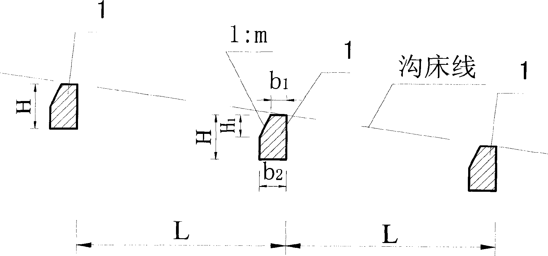
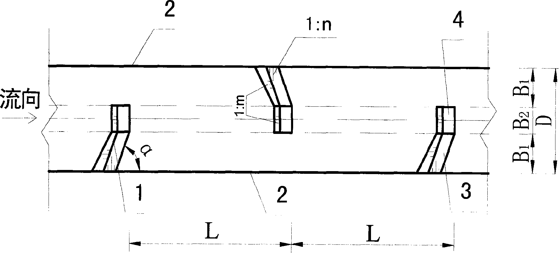
[0035] like figure 1 , figure 2 , Figure 5 shown. For a watershed area of ​​1.0km 2 , The accumulation fan slope is 16%. On the debris flow accumulation fan, the debris flow drainage channel based on the stepped anti-scour tooth sill group includes the beam side wall 2 and the stepped anti-scour tooth sill group placed therebetween, connected with it, and used in conjunction with the stepped anti-scour tooth sill group. The sill group is composed of a number of scour-proof tooth sills 1 with a certain interval and a certain buried depth. The burial depth H of the anti-scouring tooth sills 1 is 2.5m, and the distance L between the anti-scouring tooth sills 1 is 4.0m.

[0036] The lateral length B of the anti-scour tooth sills 1 forming the step anti-scour tooth sill group in the vertical direction of the beam side wall 2 is smaller than the width D of the debris flow drainage channel, and the anti-scour tooth sills forming the step anti-scour tooth sill group The scouri...

Embodiment 2

[0039] like figure 1 , image 3 , Figure 6 shown. For a watershed area of ​​8.0km 2 , The slope of the accumulation fan is 10%. The similarities with Embodiment 1 will not be repeated, and the difference is that the burial depth H of the anti-scour sills 1 is 1.8 m, and the distance L between the anti-scour sills 1 is 8.0 m.

[0040] at P 2% Under the design standard, the debris flow flow rate of the drainage channel is 68.0m 3 / s, D takes 5.0m, B takes 2.5m; inclination angle α takes 70°; slope gradient 1:n takes 1:10; top width b 1 Take 1.0m, bottom width b 2 Take 1.5m, and take 1:0.8 for the slope of the upstream side as 1:m. h 1 Take 0.63m.

Embodiment 3

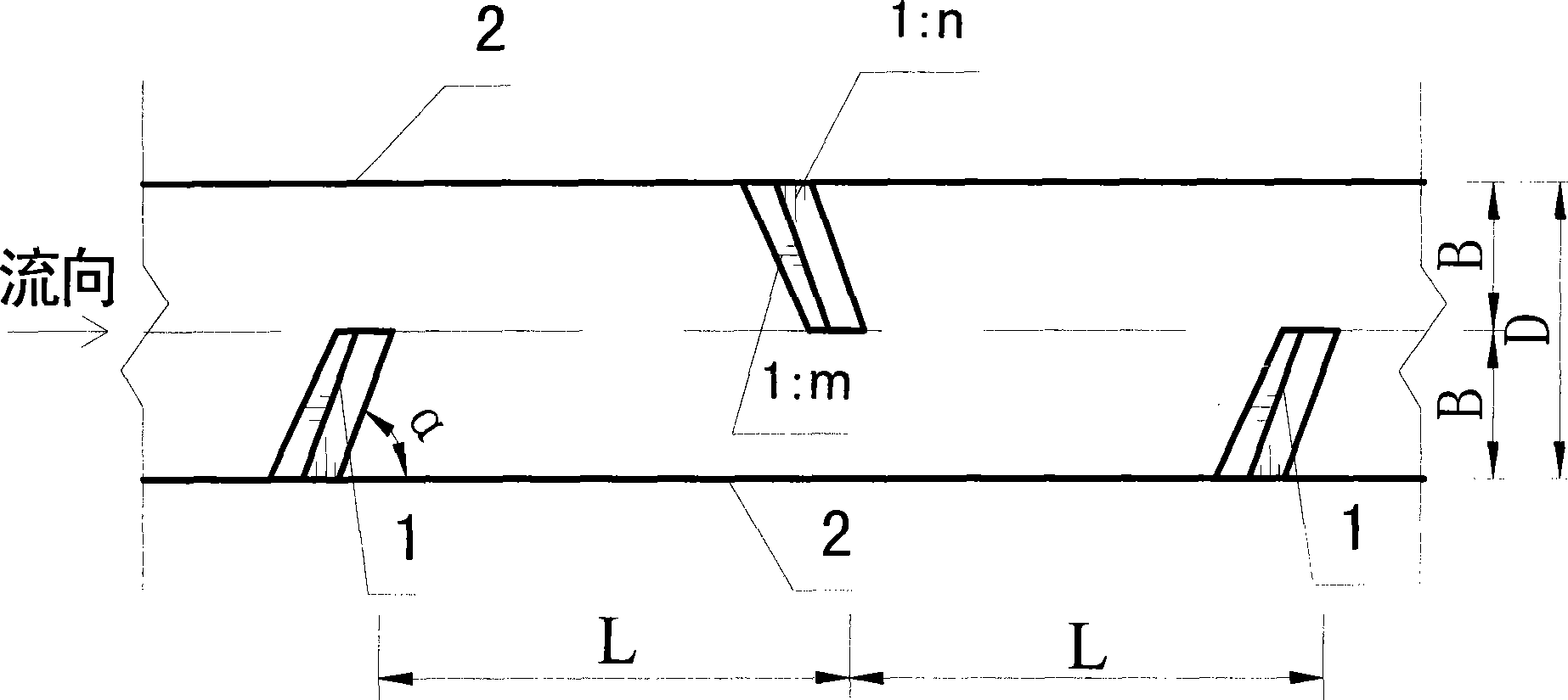
[0042] like figure 1 , Figure 4 , Figure 7 shown. For a basin area of ​​30.0km 2 , The slope of the accumulation fan is 5%. The same as the first embodiment will not be repeated, and the difference is that: the burial depth H of the anti-scour sills 1 is 1.5 m, and the distance L between the anti-scour sills 1 is 15.0 m.

[0043] at P 2% Under the design standard, the debris flow flow rate of the drainage channel is 185.0m 3 / s, D takes 16.0m, B takes 6.0m; inclination angle α takes 85°; slope gradient 1:n takes 1:20; top width b 1 Take 1.5m, bottom width b 2 Take 2.0m, and take 1:1 for the gradient 1:m at the upstream side. h 1 Take 0.5m.


PUM


Abstract

The invention discloses a debris flow draining and guiding groove based on step type erosion protection dentated sill group and application thereof. the debris flow draining and guiding groove comprises flow limiting walls, and a step type erosion protection dentated sill group disposed therein connected and cooperated therewith; the step type erosion protection dentated sill group consists of a plurality of erosion protection dentated sills imbedded in a certain depth with a certain distance therebetween; the transverse length B of the erosion protection dentated sill in the direction perpendicular to the flow limiting wall is less than the width D of the debris flow draining and guiding groove; and the erosion protection dentated sills are staggered between the two flow limiting walls. Compared with the current technologies, the invention can fully drain the debris flow safely and smoothly with low cost, can meet the requirement from structrual type mud flow to mountain torrents burst in the drainage area; and can maintain the contacting of the aquatic organisms in the groove bed to benefit the groove ecology restoration.

Description

technical field [0001] The invention relates to a mud-rock flow drainage technology, in particular to a mud-rock flow based on a mud-rock flow soft foundation energy dissipation, which is suitable for viscous mud-rock flow, or dilute mud-rock flow, or water-rock flow, or flood discharge in mountainous areas. Slots and their applications. Background technique [0002] Debris flow has a much higher bulk density than water flow, and its fluid binary structure containing clastic soil has special characteristics, such as high inertia, strong transport force, and huge impact force. The strong erosion produced by the debris flow movement leads to drastic changes in the ditch bed, causing the bottom of the ditch bed and the collapse of the ditch bank, which increases the source of solid materials to replenish the debris flow and increases the damage of the debris flow. , water canals, electricity, communication lines and other infrastructure, as well as farmland, forests and other ...

Claims


Application Information

Patent Timeline
Patent Type & Authority Applications(China)
IPC IPC(8): E02B3/04
Inventor 陈晓清游勇李德基崔鹏
Owner INST OF MOUNTAIN HAZARDS & ENVIRONMENT CHINESE ACADEMY OF SCI
Why Eureka
Try Eureka