

Ultra-large span cylindrical surface compound rods giant grid structure
A technology of grid structure and combined rods, which is applied in the direction of building structure and construction, can solve the problems of complex processing structure, increased steel consumption, and overall instability, so as to save steel consumption, reduce project cost, and improve Overall Stiffness and Stability Effects
- Summary
- Abstract
- Description
- Claims
- Application Information
AI Technical Summary
Problems solved by technology
Method used
Image

Examples
Embodiment 1
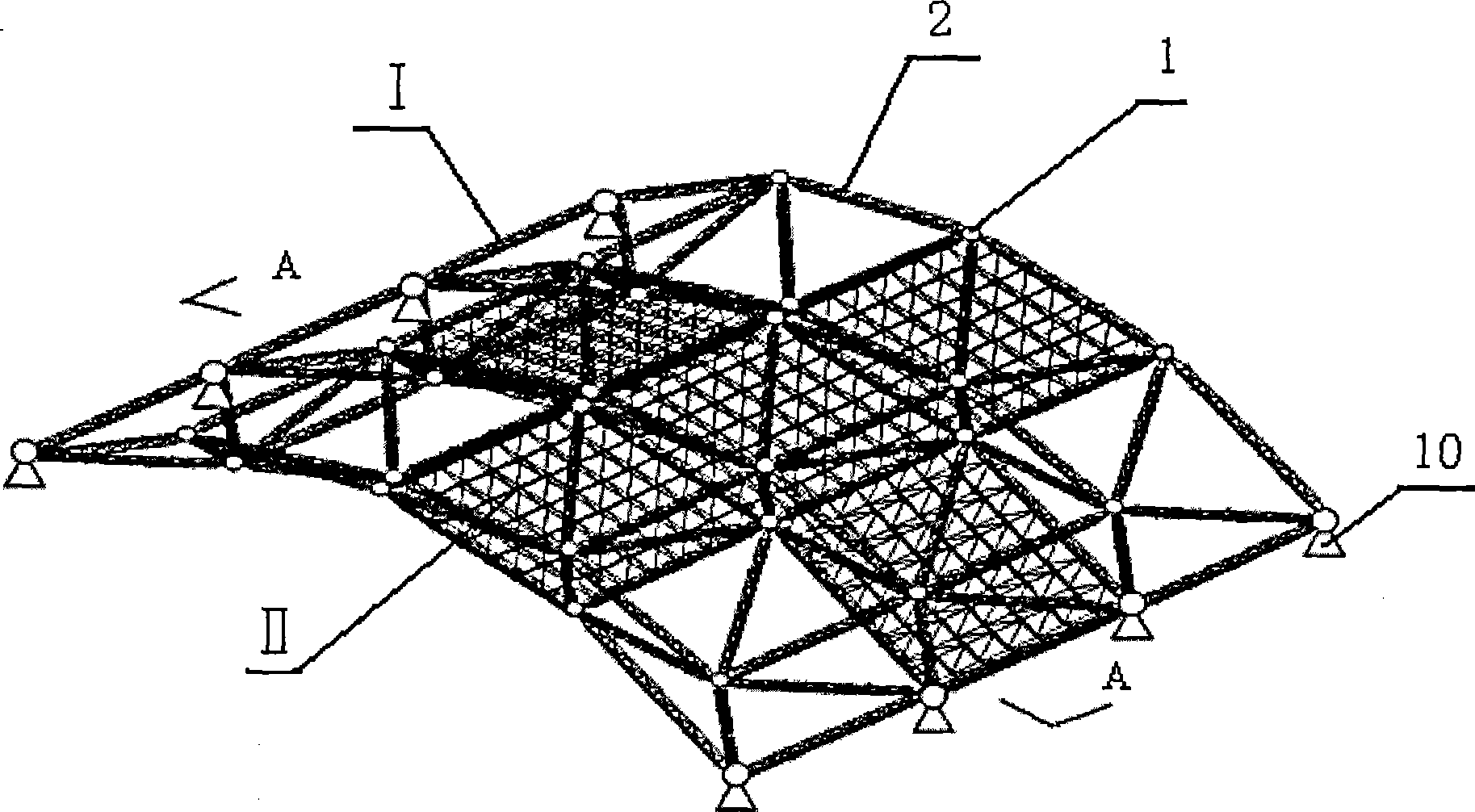
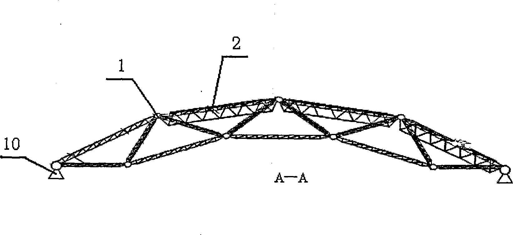
[0019] Example 1: Combining figure 1 , figure 2 , image 3 , Figure 4 :
[0020] The whole structure is composed of main structure I and substructure II arranged in the main structure. The main structure is a large grid structure composed of lattice components, and its grid size is 10-30m. The sub-structure is an ordinary double-layer flat grid, and the sub-structure is embedded in the large grid in the form of four-point support, forming a structural form of a large grid with a small grid. Supports 10 are provided on the two longitudinal sides of the main structure of the large grid. The load of the entire structure is borne by the relatively sparse and grand main structure, and then transmitted to the support 10 by the main structure.
[0021] The large grid structure composed of lattice components is composed of lattice composite rods 2 hinged and connected through large-sized welded hollow spherical nodes 1 . The lattice type combined rod of the present embodiment ...
Embodiment 2
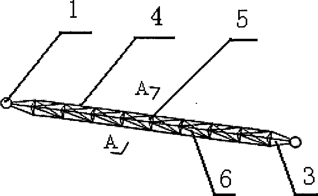
[0022] Example 2: Combining figure 1 , figure 2 , Figure 5 , Figure 6 :
[0023] The difference between this embodiment and Embodiment 1 is that the lattice type combined rod of this embodiment is a square cross-section combined rod, and its two ends are pyramid-shaped, and the outside of the middle section is formed by 4 long main pipes A bracket, a number of square diaphragms 5 perpendicular to the long main pipe and oblique web bars 6 with an inclination angle of 45-55 degrees to the diaphragm are arranged inside the bracket.
[0024] The square diaphragm is a square frame formed by four equal-length round steel pipes 8, and the square frame is connected with the long main pipe 4 through a direct intersection node. A support rod 9 is added in the regular quadrilateral frame to prevent the motor deformation of the section.
PUM
| Property | Measurement | Unit |
|---|---|---|
| Grid size | aaaaa | aaaaa |
Abstract
Description
Claims
Application Information