Combined abutment structure for temporary trestle

A combined trestle technology, applied in bridge form, portable bridge, infrastructure engineering, etc., can solve problems such as vertical deformation of trestle structure, inconvenient on-site construction and installation, and road surface cracking, so as to improve overall rigidity and stability, The effect of fast construction speed and shortened cycle

Pending Publication Date: 2020-08-21
CHINA RAILWAY NO 5 ENG GRP +1
View PDF0 Cites 1 Cited by
  • Summary
  • Abstract
  • Description
  • Claims
  • Application Information

AI Technical Summary

Problems solved by technology

For the L-shaped gravity abutment, due to the small size and poor stability of the abutment, the backfill of the abutment is prone to settlement and sliding deformation under the long-term action of load or the influence of rainwater erosion, resulting in cracking of the road surface and affecting The normal use of the trestle bridge; for the steel structure abutment, the structure is more complicated, which is not convenient for on-site construction and installation. The earth pressure on the back of the abutment is borne by the trestle structure itself, which will easily lead to longitudinal deformation of the trestle structure, making the steel pipe piles in an eccentric compression state. It is not conducive to the stability of the trestle structure

Method used


Image

  • Combined abutment structure for temporary trestle
  • Combined abutment structure for temporary trestle
  • Combined abutment structure for temporary trestle

Examples


Embodiment Construction

[0024] The embodiments of the present invention will be described in detail below with reference to the accompanying drawings, but the present invention can be implemented in many different ways defined and covered by the claims.

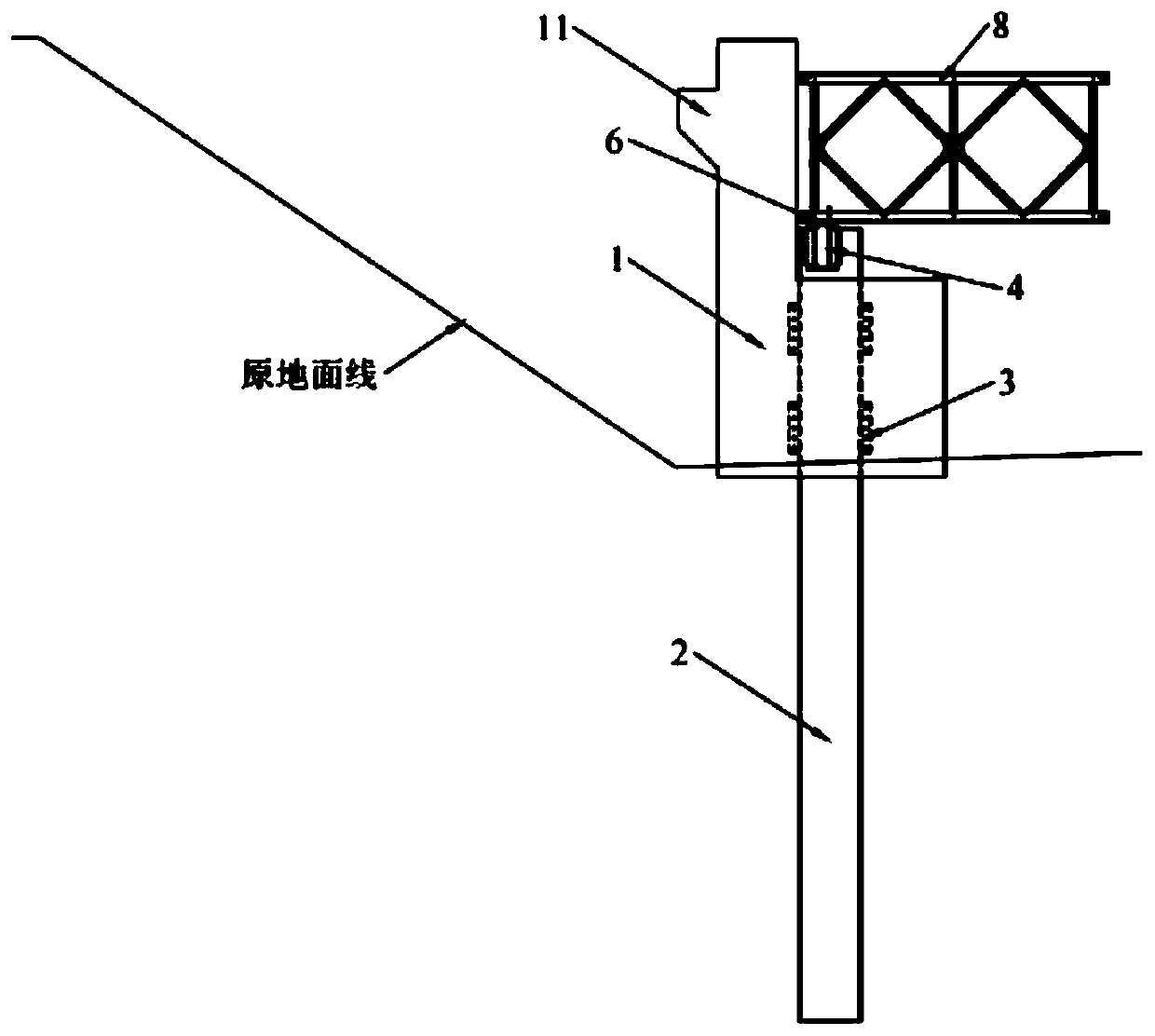
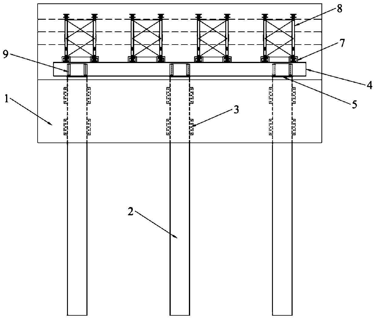
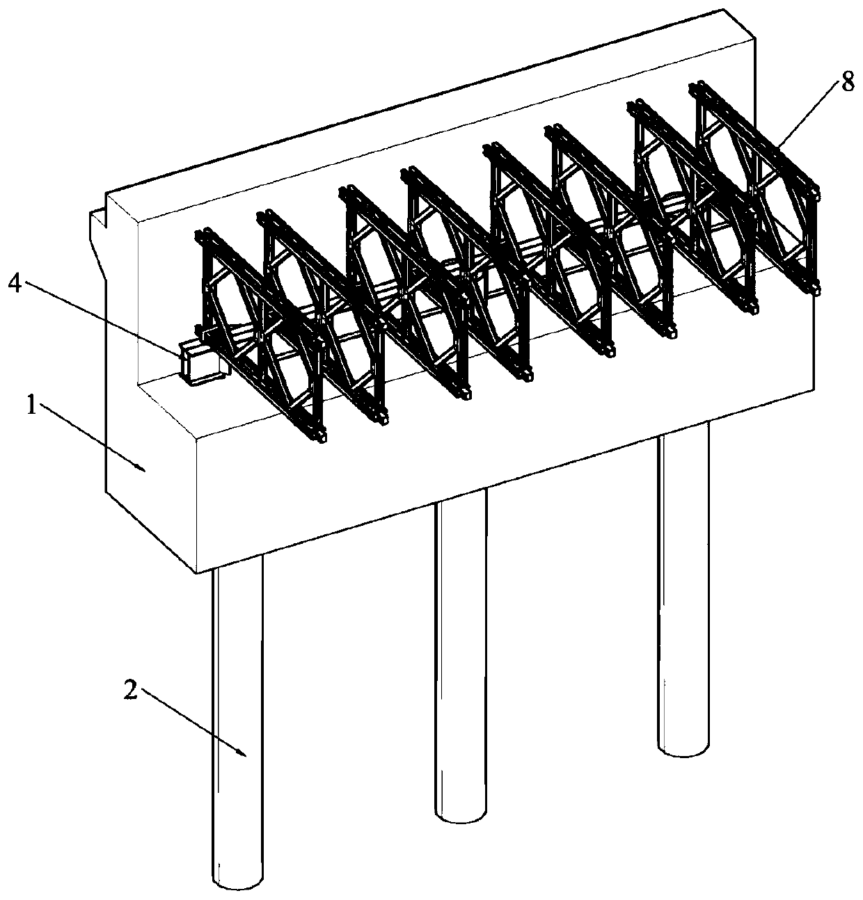
[0025] like Figure 1-5 As shown, the present invention discloses a combined abutment structure for a temporary trestle, including a pedestal 1, a steel pipe pile 2, a shear connector 3, a backing beam 4, a steel backing plate 5, a rubber pad 6, and The limit plate 7; the steel pipe pile 2 is provided with a shear connector 3 in the embedded section of the pedestal 1; The backing beam 4 is snapped inside, the steel backing plate 5 is set between the bottom surface of the backing beam 4 and the eccentric groove 10, and the rubber pad 6 is set between the top surface of the backing beam 4 and the main beam 8 of the trestle bridge for cushioning and vibration reduction; the backing beam 4 The top surface is provided with a limit plate 7 for fixing the...


PUM


Abstract

The invention discloses a combined abutment structure for a temporary trestle. The structure comprises a pedestal, a steel pipe pile, a shear connector, a bearing beam and a trestle girder. The bearing beam is mounted on the pedestal, the end part of the trestle girder is mounted on the bearing beam, the shear connector is arranged in an embedded section of the pedestal where the steel pipe pile is positioned, and the shear connector extends outwards from the steel pipe pile. The steel pipe pile and the L-shaped gravity type bridge abutment are combined, the shear connector is arranged in theembedded section of the steel pipe pile, the steel pipe pile and the L-shaped gravity type bridge abutment are stressed together, so that the overall rigidity and stability of the bridge abutment structure are improved, and sedimentation and sliding deformation of abutment back filling soil can be stably prevented.

Description

technical field [0001] The invention relates to the technical field of civil engineering, in particular to a combined abutment structure for a temporary trestle bridge. Background technique [0002] For underwater bridge projects across bays, rivers, lakes, reservoirs, etc., in order to facilitate the entry and passage of construction materials and mechanical equipment, temporary trestles must generally be set up. The structure of the temporary trestle is generally as follows: the bridge deck adopts fabricated stiffened steel bridge deck, the horizontal distribution beam adopts I-beam, the longitudinal main girder adopts Bailey beam, the horizontal load-bearing beam is arranged under the Bailey beam, and the steel pipe pile is arranged under the transverse load-bearing beam . For the sake of flood control, the design elevation of the bridge deck of the temporary trestle bridge is often level with the flood embankments on both sides, and abutments must be set at the junction...

Claims


Application Information

Patent Timeline
IPC IPC(8): E01D19/02E01D15/12E02D27/14E02D27/52E02D5/28E01D101/30E01D101/26
CPCE01D15/12E01D19/005E01D2101/26E01D2101/30E02D5/285E02D27/14E02D27/525E02D2300/0029
Inventor 伍彦斌何驰高磊郭鉷浩
Owner CHINA RAILWAY NO 5 ENG GRP
Why Eureka
Try Eureka