
Capacitor based dynamic torque sensor

A dynamic torque and sensor technology, applied in devices, instruments, torque measurement, etc. using electric/magnetic methods, can solve the problems of inability to use high speed, high precision, inability to reach a larger order of magnitude, and low precision, and achieve Simple structure, accurate measurement, and the effect of rotation angle and rotation speed

Inactive Publication Date: 2009-07-08
CHINA JILIANG UNIV
View PDF4 Cites 10 Cited by
  • Summary
  • Abstract
  • Description
  • Claims
  • Application Information

AI Technical Summary

Problems solved by technology

[0002] At present, the dynamic torque sensor mainly adopts the principle of resistance strain type. The problem of the strain type torque sensor is how to reliably transmit the torque signal and power supply detected by the strain bridge on the elastic shaft between the elastic shaft and the external static part.
However, this type of method is only suitable for the case of low speed and limited cumulative rotation angle, and because the number of plates in the source plate group used by it is limited, it cannot reach a large magnitude, so the measurement accuracy is low. It can output a certain range of rotation angle. This kind of torque sensor can only be used in specific occasions, and cannot be used in the industrial automation field with high speed and high precision requirements.

Method used


Image

  • Capacitor based dynamic torque sensor
  • Capacitor based dynamic torque sensor
  • Capacitor based dynamic torque sensor

Examples


Embodiment Construction

[0022] The present invention will be further described below in conjunction with the accompanying drawings and embodiments.

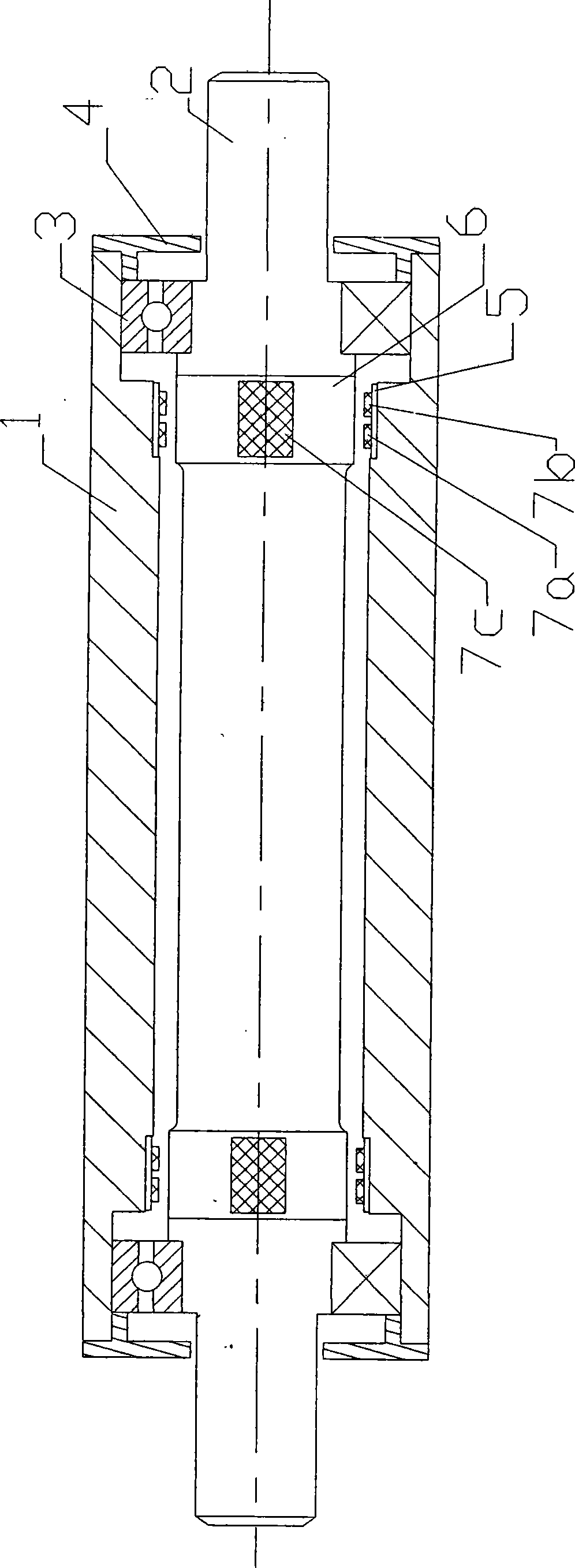
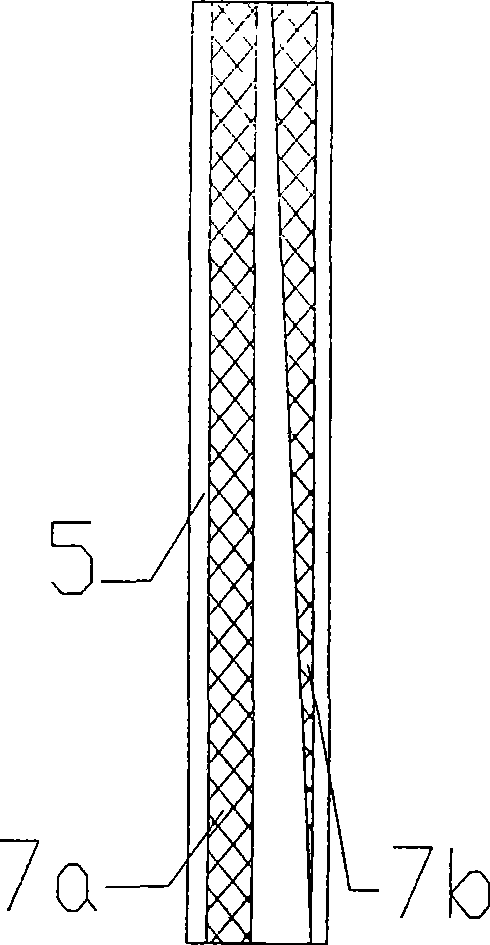
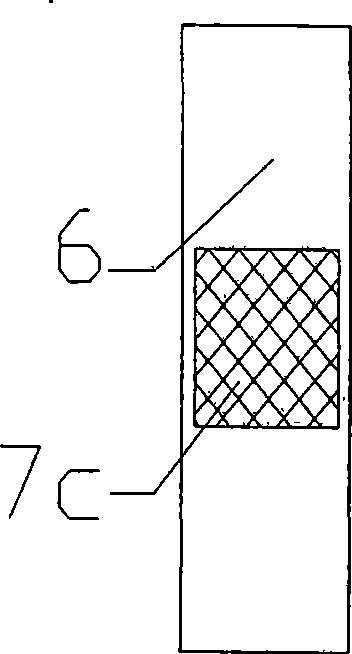
[0023] Such as figure 1 As shown, the present invention includes a housing 1, an elastic shaft 2, two bearings 3, two end caps 4, two static substrates 5, two moving substrates 6, static electrodes 7a of two excitation capacitors, two induction capacitors The static electrode 7b and two moving electrodes 7c; the elastic shaft 2 is installed in the casing 1 and supported in the bearings 3 at both ends, and the end cover 4 is covered, and the ring-shaped static substrate 5 is embedded in the hole of the casing 1 near the inner side of the bearings 3 at both ends. The inner ring of the embedded ring static substrate 5 is sequentially equipped with the static electrode 7b of the induction capacitor and the static electrode 7a of the excitation capacitor from the outside to the inside in the axial direction, and the two ends corresponding to the static elect...


PUM


Abstract

The invention discloses a dynamic torque sensor based on capacitance, which comprises a shell, an elastic shaft, two bearings, two static substrates, two dynamic substrates and two capacitor sets which consist of two excitation capacitance static electrodes, two inductance capacitance static electrodes and two dynamic electrodes and are symmetrically arranged at both ends of the elastic shaft. Along with the rotation of the shaft, the relative position of the shaft and the shell is changed, and capacitance signals of the capacitance sets, which are symmetrically arranged at both ends of the shaft, are changed according to a certain regular period. When the elastic is rotated by torque force, the capacitance signals at both ends of the shaft can generate a phase difference, and a relation between a capacitance difference and a torque is established by detecting the capacitance difference value so as to achieve the measurement of the torque, the rotating angle and the rotating speed. The dynamic torque sensor has the advantages of no contact, high precision, low cost and long service life, and is suitable for the industrial automation field of high rotating speed environment.

Description

technical field [0001] The present invention relates to torque sensors, in particular to a capacitance-based dynamic torque sensor. Background technique [0002] At present, the dynamic torque sensor mainly adopts the principle of resistance strain type. The problem of the strain type torque sensor is how to reliably transmit the torque signal and power source detected by the strain bridge on the elastic shaft between the elastic shaft and the external static part. The current common practice is the collector ring method or the inductive coupling method. For example, the high-precision strain gauge torque sensor shown in the Chinese patent ZL96238424.0 uses the collector ring transmission technology, because the collector ring transmission technology belongs to contact transmission. There are defects such as mechanical friction, heat generation, short life and high cost. It is only suitable for short-term low-precision measurement. The strain-type inductive coupling transfer...

Claims


Application Information

Patent Timeline
Patent Type & Authority Applications(China)
IPC IPC(8): G01L3/04G01B7/30G01P3/46
Inventor 蒋庆蔡晋辉沈培璐姚燕
Owner CHINA JILIANG UNIV
Learn More