Linear induction repelling float motor

A linear induction, motor technology, applied in the direction of electric components, electrical components, electromechanical devices, etc., can solve the problem of difficulty in power supply for high-speed moving parts, and achieve the effects of simple structure, economical cost, and simple structure of the mover.

Inactive Publication Date: 2009-07-08
SOUTHEAST UNIV
View PDF0 Cites 8 Cited by
  • Summary
  • Abstract
  • Description
  • Claims
  • Application Information

AI Technical Summary

Problems solved by technology

[0005] For linear synchronous motors and long secondary linear induction motors, the high-speed moving part needs powe

Method used


Image

  • Linear induction repelling float motor
  • Linear induction repelling float motor

Examples


Embodiment Construction

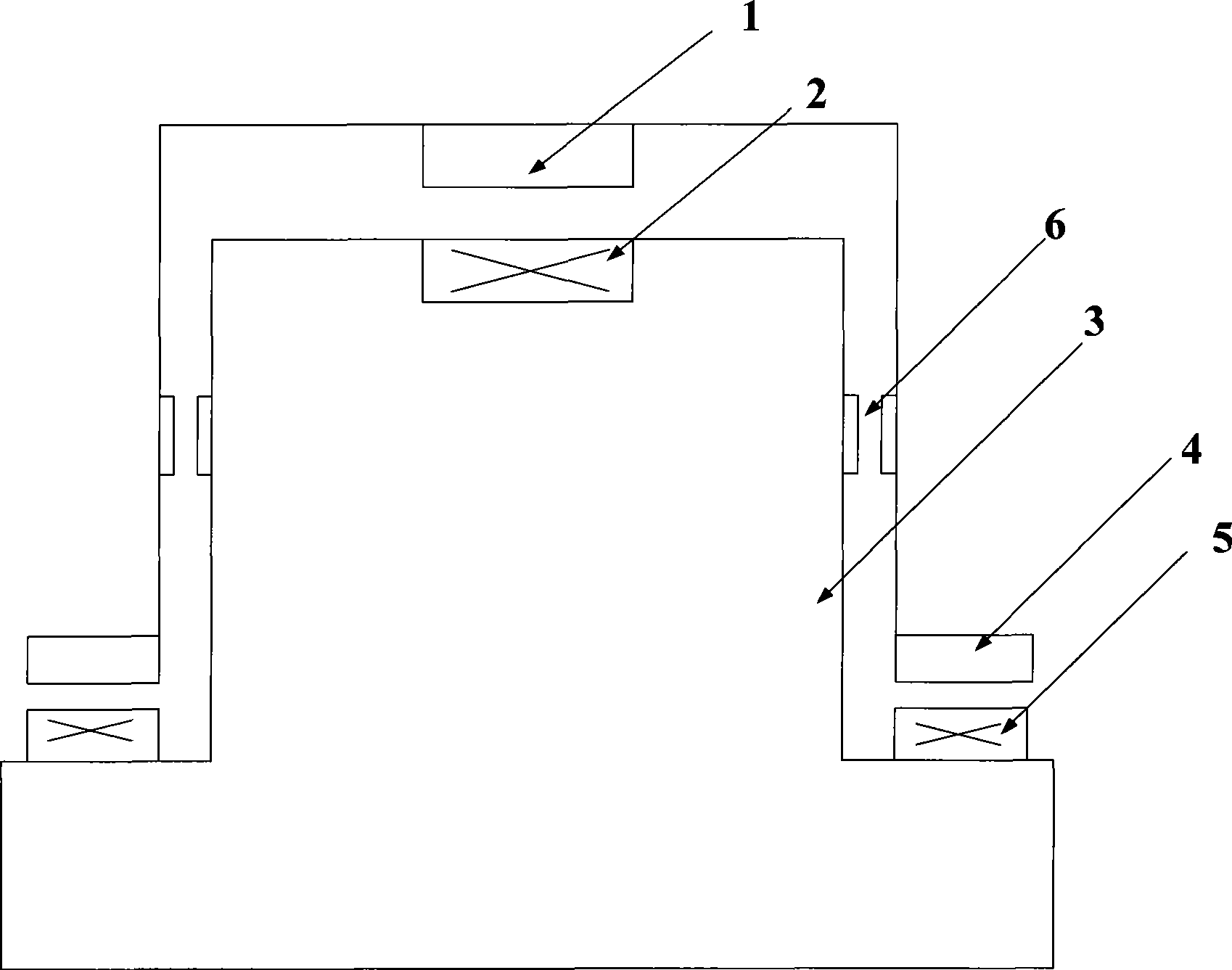
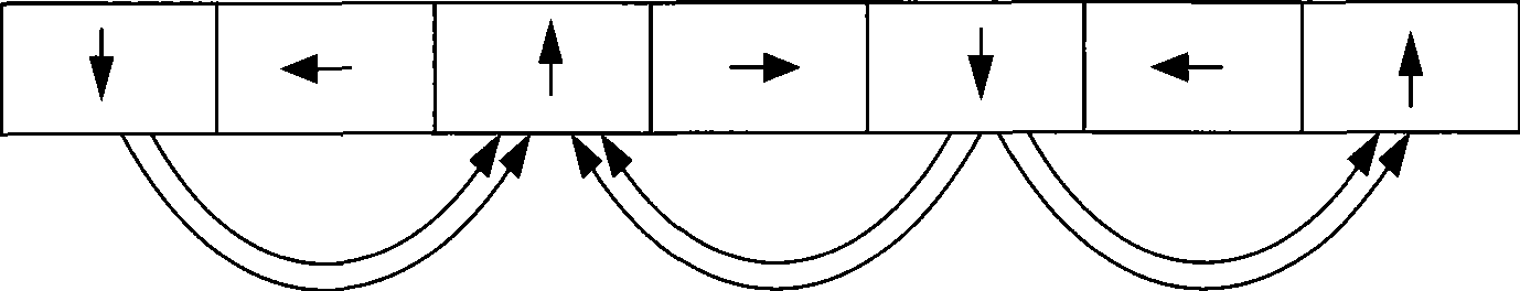
[0016] Below in conjunction with accompanying drawing, the present invention is described in detail, as figure 1 As shown, the linear induction repelling and floating motor of the present invention includes a linear induction repelling and floating motor, including a mover core 1, a stator base 3, a stator winding 2, a suspension permanent magnet 4, an exciting winding 5 and a guide magnet 6, and the stator winding 2 Set on the upper end of the stator base 3 to drive the mover core 1 to rotate, the floating permanent magnet 4 is set opposite to the excitation winding 5, wherein the suspension permanent magnet 4 is set on the stator base 2, and the excitation winding 5 is set on the mover core 1 , the suspension permanent magnet 4 is an array permanent magnet arranged horizontally and vertically, also known as a Halbach array, and the magnetic field strength on the side opposite to the magnetic force winding 5 is higher than that on the other side of the permanent magnet. When t...


PUM


Abstract

The invention discloses a linear induction repulsion buoyancy motor comprising a mover core, a stator base, a stator winding, a suspended permanent-magnet and an excitation winding. The stator winding is arranged at the upper end of the stator base and drives the mover core to rotate; the suspended permanent-magnet and the excitation winding are arranged oppositely, wherein, the suspended permanent-magnet is arranged on a mover; the excitation winding is arranged on the stator base; the suspended permanent-magnet is an array permanent-magnet that is arranged horizontally and vertically; and the magnetic density of the suspended permanent-magnet on the side opposite to a magnetic winding is stronger than that of the other side of the permanent-magnet. In the linear induction repulsion buoyancy motor, the Halbach array permanent-magnet is installed on the mover, the repulsion buoyancy is formed by the array permanent-magnet and the excitation winding on the stator base during the moving process, so the mover suspends with no contact and no friction, and can run at a high speed under the action of traction force. By adopting a unilateral primary linear induction motor, the invention solves the problem that a moving part is not easy to supply the electrical source in magnetic suspension launch.

Description

technical field [0001] The invention belongs to a novel device of a linear motor. This technology can be applied to the technical fields of high-speed trains, numerical control machine tools, and maglev launching. The core of this technology is to use Halbach permanent magnets and short-circuit coils to generate repulsive buoyancy, so that the stator and moving parts have no contact, no friction, and the operation process is safe and controllable. The principle of single-sided linear induction motor is used to provide traction thrust. Background technique [0002] Maglev launches and high-speed maglev trains are applications of linear motors. When high-speed maglev trains and maglev launches are running, they rely on electromagnetic attraction or electric repulsion to suspend the car body in the air without mechanical contact with the track, and rely on the electromagnetic thrust generated by the linear motor to realize the train. traction. They attract more and more atte...

Claims


Application Information

Patent Timeline
IPC IPC(8): H02N15/00H02K1/27H02K41/02
Inventor 余海涛黄磊李锋庄英超胡敏强
Owner SOUTHEAST UNIV
Why Eureka
Try Eureka