Pipe joint

A pipe joint and pipe body technology, which is applied in the direction of connection, rod connection, and connecting components, etc., can solve the problems of easy accumulation of dirt, falling off, and poor appearance of the pipe body connection.

Inactive Publication Date: 2009-07-08
YAZAKI IND CHEM CO LTD
View PDF2 Cites 10 Cited by
  • Summary
  • Abstract
  • Description
  • Claims
  • Application Information

AI Technical Summary

Problems solved by technology

However, in order to rotate and operate the aforementioned bolts, a plurality of perforations for inserting the tool for rotating the aforementioned bolts must be provided at the joint body. And dirt is easy to accumulate
Also, even bolts that were once tightly locked may loosen and come off during long-term use

Method used


Image

  • Pipe joint
  • Pipe joint
  • Pipe joint

Examples


Embodiment 1

[0106] Hereinafter, the present invention will be described with reference to the illustrated embodiments.

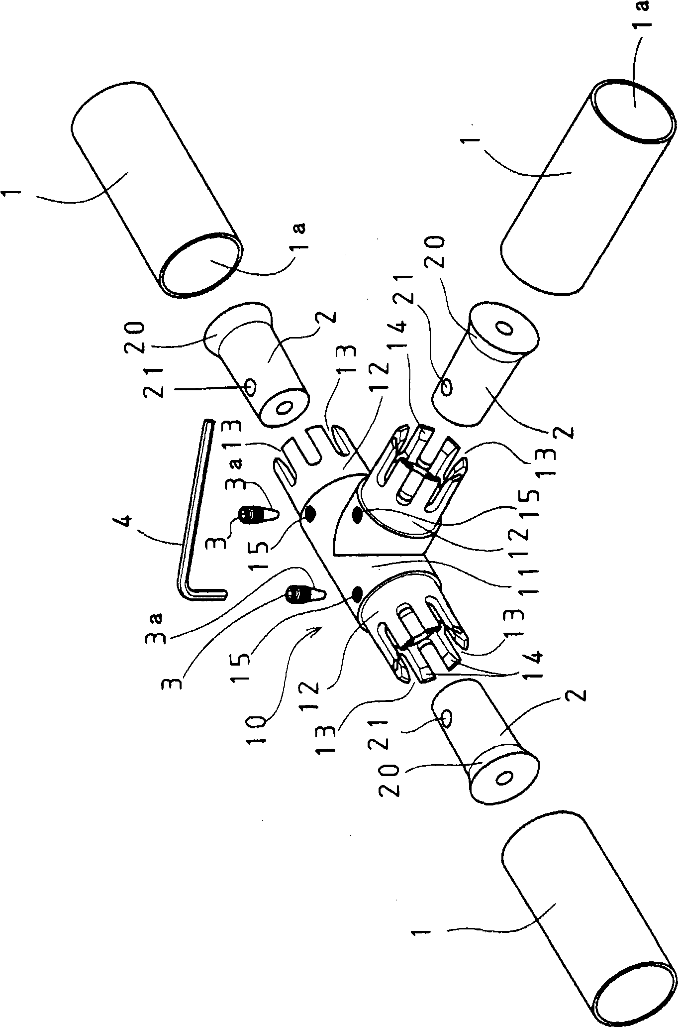
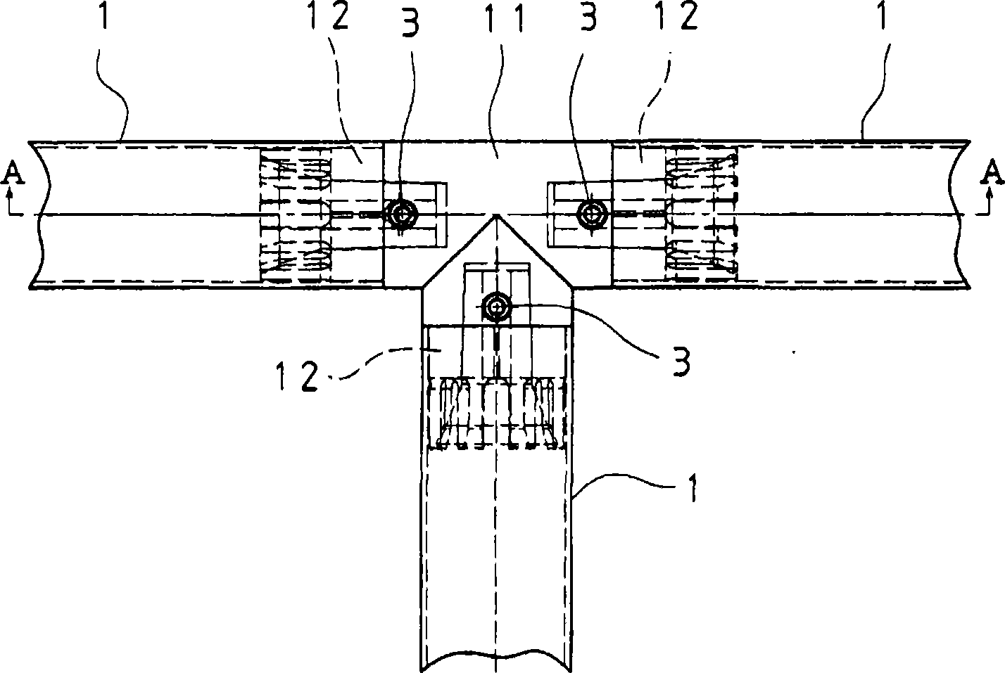
[0107] At first, Fig. 1-Fig. 3 are the embodiments of item 1 and item 2 in the present invention. In the case of the pipe body joint 10 of this embodiment, it protrudes from the joint body 11 and is inserted into the inner diameter portion 1a of the pipe body 1 that must be connected. In the embodiment of FIG. 1 , the three connection insertion parts 12 are hollow. structure. At the aforementioned insertion portion 12, the slit-shaped notches 13 that are nearly the entire length of the insertion portion 12 from its tip to the axial direction are formed in a plurality of substantially equal pitches in the circumferential direction, and the aforementioned insertion portion 12 is formed at Flexibility is given in the radial direction. The flexibility of the insertion portion 12 is to facilitate the insertion into the inner diameter portion 1a of the tubular body 1, and i...

Embodiment 2

[0126] Next, Fig. 7 shows an embodiment of the present invention described in item 3 and item 4 of the present invention.

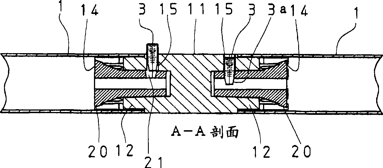
[0127] The basic structure of the joint of the present embodiment 2 (Fig. 7) has a lot in common with the above-mentioned embodiment 1. That is, the connection insertion portion 12 protruding from the joint main body 11 and inserted into the inner diameter portion of the tubular body 1 to be connected has a hollow structure. At the aforementioned insertion portion 12, a plurality of slit-like notches with roughly equal pitches are formed in the circumferential direction from its tip to the axial direction, and at the hollow portion of the aforementioned insertion portion 12, an inner diameter is formed from the tip end thereof. The tapered portion 14 narrows toward the joint body 11. The joint is composed of a tapered sleeve 2 inserted into the hollow of the connection insertion portion 12 of the joint body 11, and a fixing bolt 3 having a tapered tapered ...

Embodiment 3

[0137] Next, Fig. 8 shows an embodiment of the present invention described in item 5 and item 6 of the present invention.

[0138] The joint of this embodiment 3 is also common to the above-mentioned embodiments 1 and 2 in many basic configurations. That is, the connection insertion portion 12 that protrudes from the joint body 11 and is inserted into the inner diameter portion of the pipe body 1 that must be connected has a hollow structure. At the aforementioned insertion portion 12, a plurality of slit-like notches with roughly equal pitches are formed in the circumferential direction from its tip to the axial direction, and, at the hollow portion of the aforementioned insertion portion 12, an inner diameter is formed from the tip end thereof. The tapered portion 14 narrows toward the joint body 11. The joint is composed of a tapered sleeve 2 inserted into the hollow of the connection insertion portion 12 of the joint body 11, and a fixing bolt 3 having a tapered tapered p...


PUM


Abstract

The invention provides a tube body for a light load, specifically, a fit in type joint suitable for connecting tube bodies to assemble them into a flat or a three-dimensional tube body structure, resin adhered / coated tube bodies each formed by adhering and coating a thin layer of a synthetic resin on the outer periphery of a thin wall steel tube having an outer diameter in a range from 28mm to 45mm. The fit in type joint is constructed from a joint body, tapered sleeves, and fixation bolts. The joint body has one or more connecting insertion sections formed in a hollow structure, projected from the joint body, and inserted into the bores of tube bodies that are to be connected, each insertion section having a plurality of axially long slits formed running from the forward end of the insertion section and arranged in the circumferential direction, each insertion section having a tapered section on the hollow section thereof, the tapered section having a bore diameter reduced from the forward end section of the insertion section toward the joint body. The tapered sleeves are inserted into the hollow sections of the insertion sections. The fixation bolts secure the tapered sections to the forward end sections.

Description

technical field [0001] The present invention relates to a pipe body mainly used for light loads, specifically, it provides a pipe body which is very suitable for adhering a thin layer of synthetic resin on the outer peripheral surface of a thin-walled steel pipe, and the outer diameter is The left and right resin-coated steel pipes are assembled and connected (or connected) into an embedded pipe joint of a planar or three-dimensional pipe structure. In more detail, it is about a pipe with high connection strength and a connection The appearance behind the pipe body is a simple pipe joint. Background technique [0002] In the past, the above-mentioned light-duty pipe body is assembled into a pipe body connection joint of a planar or three-dimensional pipe body structure. well known. In the case of an externally embedded joint, refer to the A-A' enlarged cross-sectional view of Patent Document 1. The joint plug is larger than the outer diameter of the tube and is exposed fo...

Claims


Application Information

Patent Timeline
Patent Type & Authority Applications(China)
IPC IPC(8): F16B7/04E04B1/58
CPCF16B7/042F16B7/0453E04B1/585Y10T403/405
Inventor 箕轮勇矢崎敦彦
Owner YAZAKI IND CHEM CO LTD
Why Eureka
Try Eureka