
Thin film evaporator with film-climbing, film-falling and separating functions

An evaporator and thin-film technology, which is applied in the field of thin-film evaporators, can solve the problems of difficult cleaning of the deflector, damage to the stability of the evaporation system, and controllability of the easy-to-break liquid medicine, so as to reduce cross-contamination and facilitate automatic Control operation and make full use of thermal energy

Inactive Publication Date: 2010-12-15
何建桐
View PDF1 Cites 0 Cited by
  • Summary
  • Abstract
  • Description
  • Claims
  • Application Information

AI Technical Summary

Problems solved by technology

Determined by the evaporation principle of the thin-film evaporator, the liquid level height of the heating tube entering the evaporation interlayer of the thin-film evaporator is limited, otherwise it cannot be effectively heated in the evaporation interlayer of the thin-film evaporator The liquid film is formed on the tube wall, which easily destroys the controllability of the water in the liquid film and destroys the stability of the entire evaporation system. Moreover, so far, there is no reliable automatic flow control The device technology can achieve the purpose of stably controlling the flow of liquid medicine under complex and changeable conditions
Moreover, the deflector on the main body is fixed and difficult to clean

Method used


Image

  • Thin film evaporator with film-climbing, film-falling and separating functions
  • Thin film evaporator with film-climbing, film-falling and separating functions
  • Thin film evaporator with film-climbing, film-falling and separating functions

Examples


Embodiment Construction

[0013] Now in conjunction with accompanying drawing and embodiment the present invention is described in further detail:

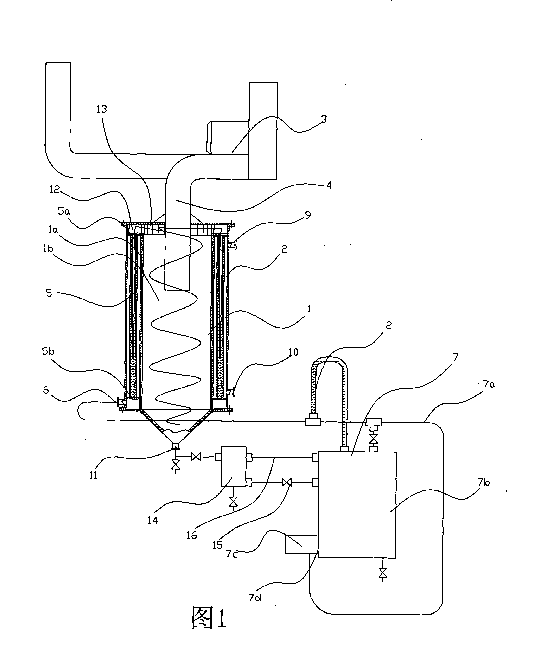
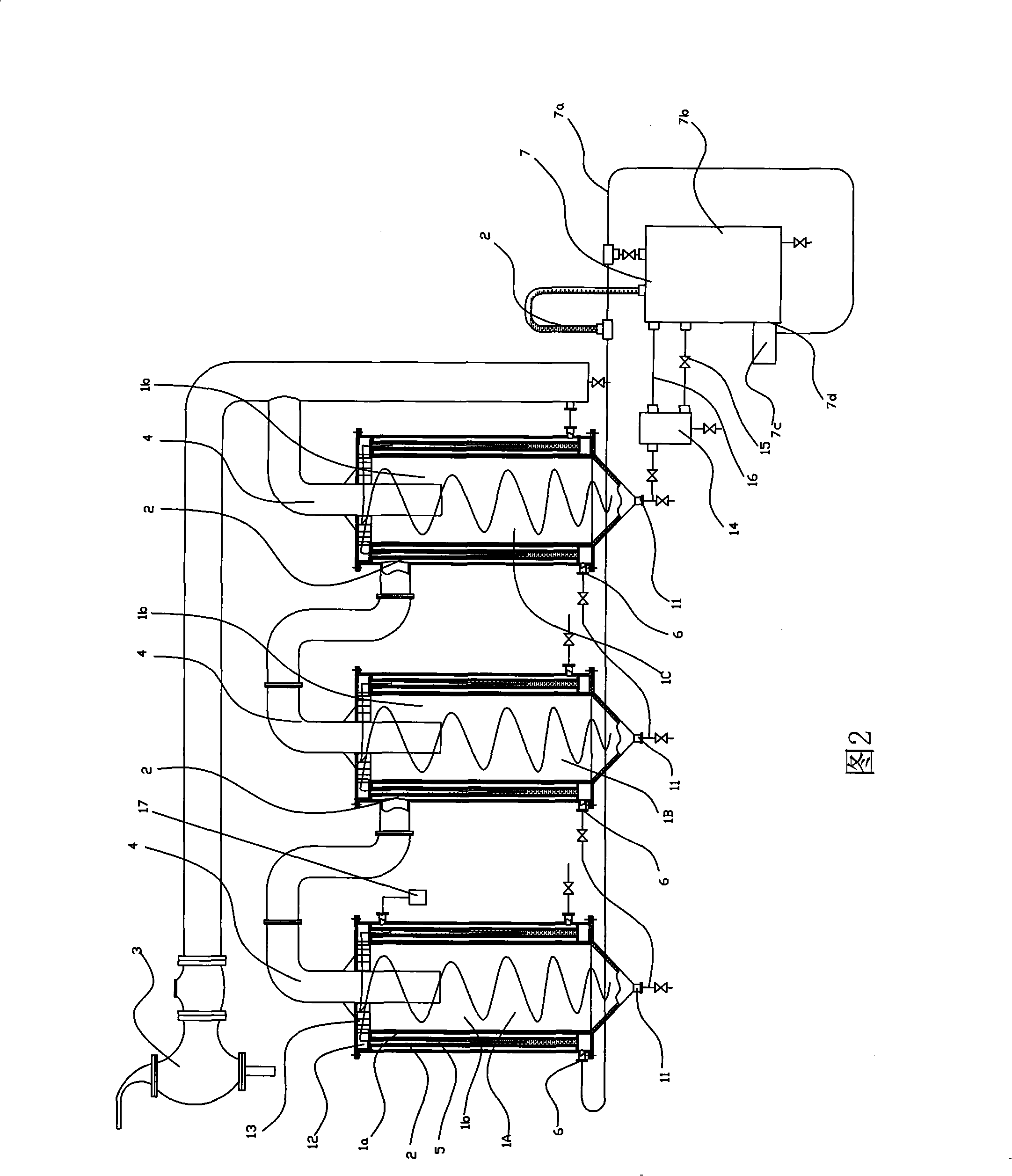
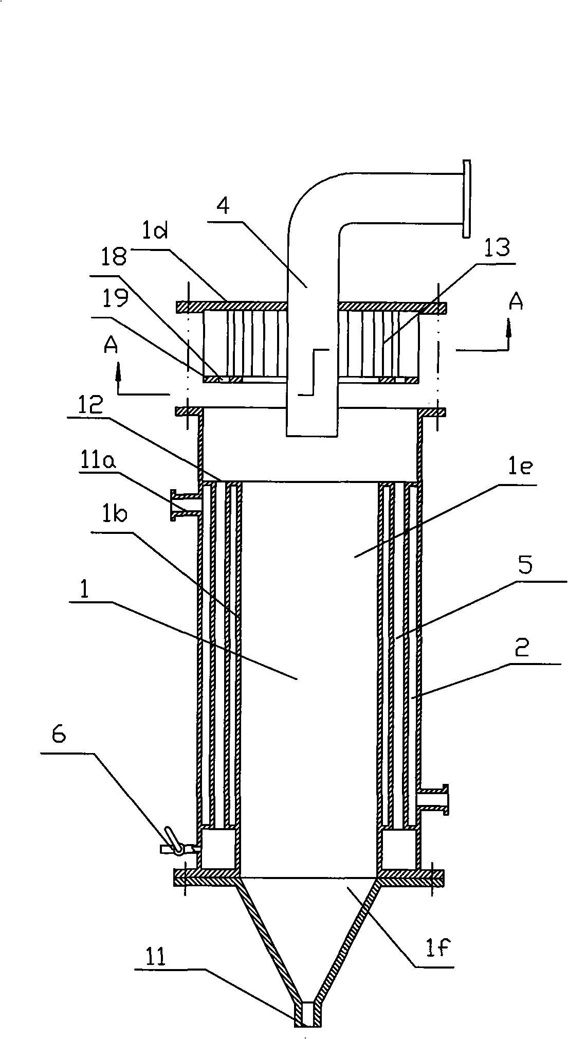
[0014] As shown in the figure, the present invention includes a cylindrical evaporator main body 2 with an interlayer 2 on the side wall 1a, a steam suction pipe 4 connected to a vacuum suction device 3 that goes deep into the inner cavity 1b of the cylindrical evaporator main body 1, and a vapor suction pipe 4 located in the interlayer 2. The inner upper port 5a communicates with the inner cavity 1b of the cylindrical evaporator main body 1, the lower port 5b communicates with the heating tube 5 connected with the liquid medicine inlet 6, the medicine liquid delivery device 7 communicated with the medicine liquid inlet 6, and the medicine liquid delivery device 7 located in the medicine liquid The liquid level control device 8 on the delivery pipe 7a of the liquid delivery device 7, the interlayer 2 communicates with the high-temperature steam delivery por...


PUM


Abstract

The invention relates to a film type evaporator with film climbing, film falling and separating functions, which is characterized by comprising a barrel-shaped evaporator main body with an interlayer on the lateral wall, a steam suction tube which is connected with a vacuum suction device and penetrates into the inner cavity of the barrel-shaped evaporator main body, a heating tube with an upper port communicated with the inner cavity of the barrel-shaped evaporator main body and a lower port communicated with a liquor inlet positioned in the interlayer, a liquor delivery device communicated with the liquor inlet, and a liquid level control device positioned on the delivery tube of the liquor delivery device; the interlayer is communicated with a high-temperature steam delivery port; a condensed water discharge device is arranged at the lower end of the interlayer; a concentrated liquor outlet is arranged at the lower end of the inner cavity of the barrel-shaped evaporator main body; the liquor delivery device comprises a liquor barrel, a liquor supply pump and the delivery tube; and the liquor outlet under the liquor barrel is communicated with the liquor inlet through the liquorsupply pump and the delivery tube. Compared with the prior art, the invention has the advantages that a stable and controllable evaporating system is ensured, and the heat energy can be utilized fully.

Description

Technical field: [0001] The invention relates to a thin film evaporator. Background technique: [0002] An existing thin-film evaporator, as disclosed in patent 99245615.0, the flow rate of the liquid medicine entering the thin-film evaporator is controlled by an automatic flow control device, and the pressure of the steam is used to switch and activate the flow rate to control the liquid medicine flow rate. When the steam pressure is high, the flow rate of the liquid medicine is large, and when the steam pharmacology provided is small, the flow rate of the liquid medicine is small. Determined by the evaporation principle of the thin-film evaporator, the liquid level height of the heating tube entering the evaporation interlayer of the thin-film evaporator is limited, otherwise it cannot be effectively heated in the evaporation interlayer of the thin-film evaporator The liquid film is formed on the tube wall, which easily destroys the controllability of the water in the liq...

Claims


Application Information

Patent Timeline
Patent Type & Authority Patents(China)
IPC IPC(8): B01D1/22
Inventor 何建桐
Owner 何建桐
Learn More