Power transmission control device, non-contact power transmission system, power transmitting device, electronic instrument, and waveform monitor circuit

A power transmission device and power transmission technology, applied in circuit devices, electromagnetic wave systems, battery circuit devices, etc., to achieve accurate initial fault detection, improve reliability, safety, and stability.

Inactive Publication Date: 2009-07-15
SEIKO EPSON CORP
View PDF1 Cites 14 Cited by
  • Summary
  • Abstract
  • Description
  • Claims
  • Application Information

AI Technical Summary

Problems solved by technology

However, various circuits may be connected to the primary coil

Method used


Image

  • Power transmission control device, non-contact power transmission system, power transmitting device, electronic instrument, and waveform monitor circuit
  • Power transmission control device, non-contact power transmission system, power transmitting device, electronic instrument, and waveform monitor circuit
  • Power transmission control device, non-contact power transmission system, power transmitting device, electronic instrument, and waveform monitor circuit

Examples


no. 1 approach

[0073] First, examples of preferable electronic equipment to which the present invention is applied and the principle of non-contact power transmission technology will be described.

[0074] (Examples of electronic devices and principles of contactless power transmission)

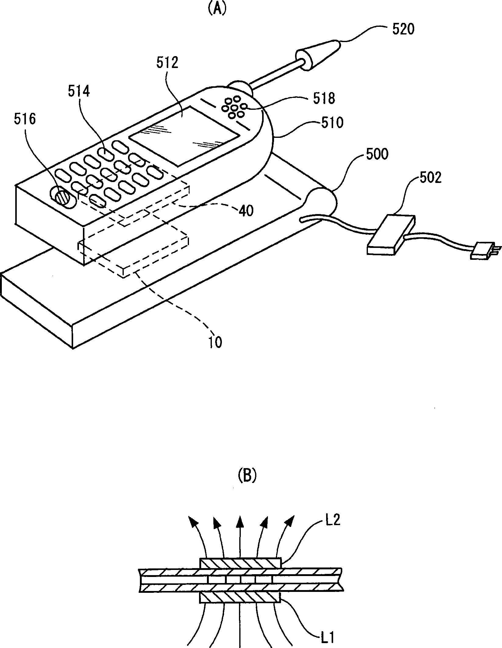
[0075] figure 1 (A) and figure 1 (B) is an explanatory diagram for explaining an example of an electronic device to which the non-contact power transmission method is applied and the principle of the non-contact power transmission using an induction transformer.

[0076] Such as figure 1 As shown in (A), a charger (cradle) 500 as a power transmission-side electronic device includes a power transmission device (such as a power transmission module including a power transmission-side control circuit (power transmission-side control IC)) 10 .

[0077] A mobile phone 510 as a device on the power receiving side has a power receiving device (a power receiving module including a power receiving side control c...

no. 2 approach

[0174] In this embodiment, an example of a specific circuit configuration of the power transmission unit will be described.

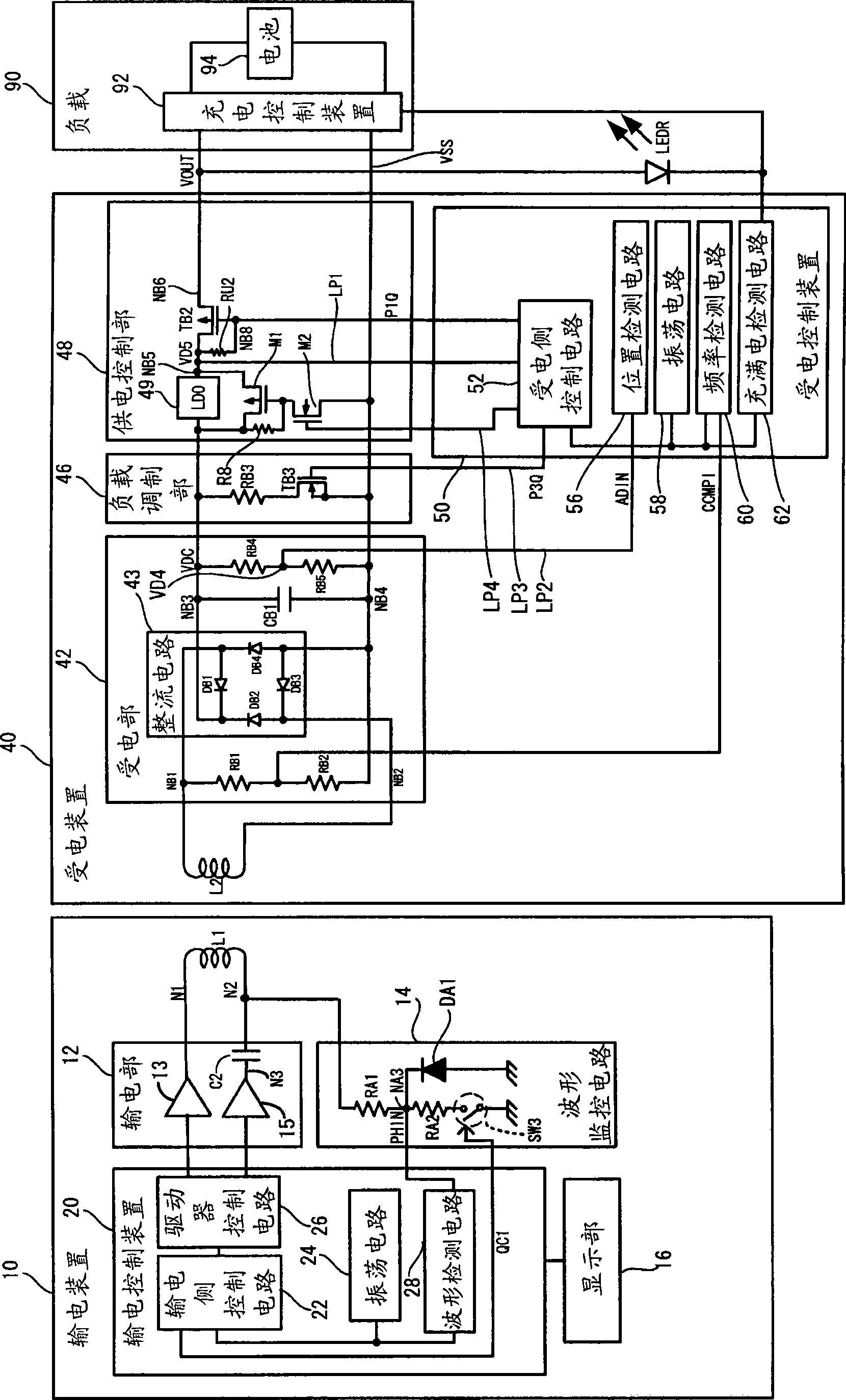
[0175] (Example of the specific internal circuit configuration of the power transmission control device and the power transmission unit)

[0176] Figure 10 It is an example block diagram showing the specific internal circuit configuration of the power transmission control device and the power transmission unit. exist Figure 10 in, with figure 2 The same parts are marked with the same reference numerals. exist Figure 10 Among them, a switch SW3 is provided in the waveform monitoring circuit 14, and the switch SW3 is turned off when an initial failure is detected. and, in Figure 10 Among them, the switch SW3 provided in the waveform monitoring circuit 14 is composed of an NMOS transistor MSK. On / off of the NMOS transistor MSK is controlled by a timing control circuit 33 provided in the power transmission side control circuit 22 . The operatio...


PUM


Abstract

A power transmission control device includes a power-transmitting-side control circuit that controls an operation of a power transmitting device, a driver control circuit that controls operations of a first power transmitting driver and a second power transmitting driver, and a waveform detection circuit that performs a waveform detection process based on a monitor signal from a waveform monitor circuit. The first power transmitting driver drives a first node of a primary coil directly, and the second power transmitting driver drives a second node of the primary coil through a capacitor. A switch circuit is provided in the waveform monitor circuit, the switch circuit being situated in a signal path between the primary coil and a low-level power supply potential. The power-transmitting-side control circuit causes the switch circuit to be turned ON / OFF using a switch control signal.

Description

technical field [0001] The invention relates to a power transmission control device, a non-contact power transmission system, a power transmission device, electronic equipment, a waveform monitoring circuit and the like. Background technique [0002] In recent years, non-contact power transmission (non-contact power transmission) that enables power transmission without contact of metal parts by using electromagnetic induction has attracted attention. As an example of application of this non-contact power transmission, charging of mobile phones and household appliances (for example, handsets of telephones) and the like have been proposed. [0003] A non-contact power transmission device using a primary coil and a secondary coil is described in Patent Document 1, for example. In the non-contact power transmission system described in Patent Document 1, a driver with a CMOS structure (CMOS driver) is used as a driver for driving the primary coil, and a control circuit for preve...

Claims


Application Information

Patent Timeline
Patent Type & Authority Applications(China)
IPC IPC(8): H02J17/00H02M7/02H02J7/00H02M5/00H02M7/48
Inventor 大西幸太神山正之盐崎伸敬上条贵宏
Owner SEIKO EPSON CORP
Why Eureka
Try Eureka