Power generation machine for switched reluctance motor

A technology of switched reluctance motors and generators, applied to electrical components, electromechanical devices, electric components, etc., to achieve the effects of reducing switching power consumption, continuous current, and improving power generation performance and efficiency

Inactive Publication Date: 2009-07-15
张世清
View PDF1 Cites 13 Cited by
  • Summary
  • Abstract
  • Description
  • Claims
  • Application Information

AI Technical Summary

Problems solved by technology

[0003] However, since the switched reluctance motor rotor has no coil windings, the complexity of the switched reluctance motor generator is increased, that is, the stator winding is both an excitation winding and a power generation winding. When each phase winding is energized in turn, the motor will generate electromagnetic torque. , so that the motor rotates continuously, its power generation efficiency has certain limitations

Method used


Image

  • Power generation machine for switched reluctance motor
  • Power generation machine for switched reluctance motor
  • Power generation machine for switched reluctance motor

Examples


Embodiment 1

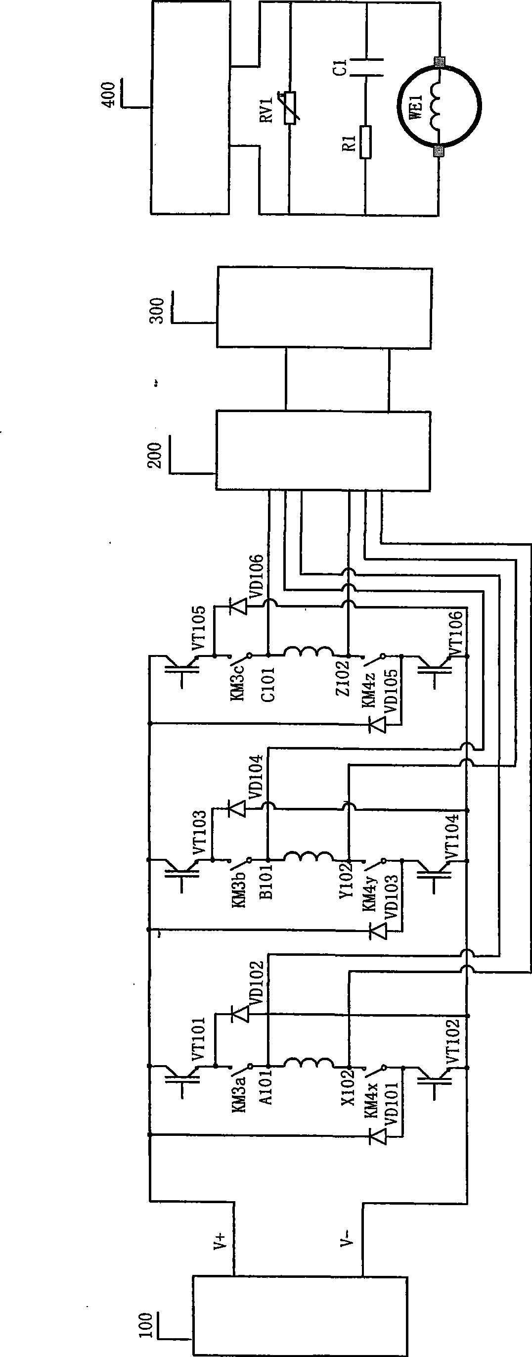
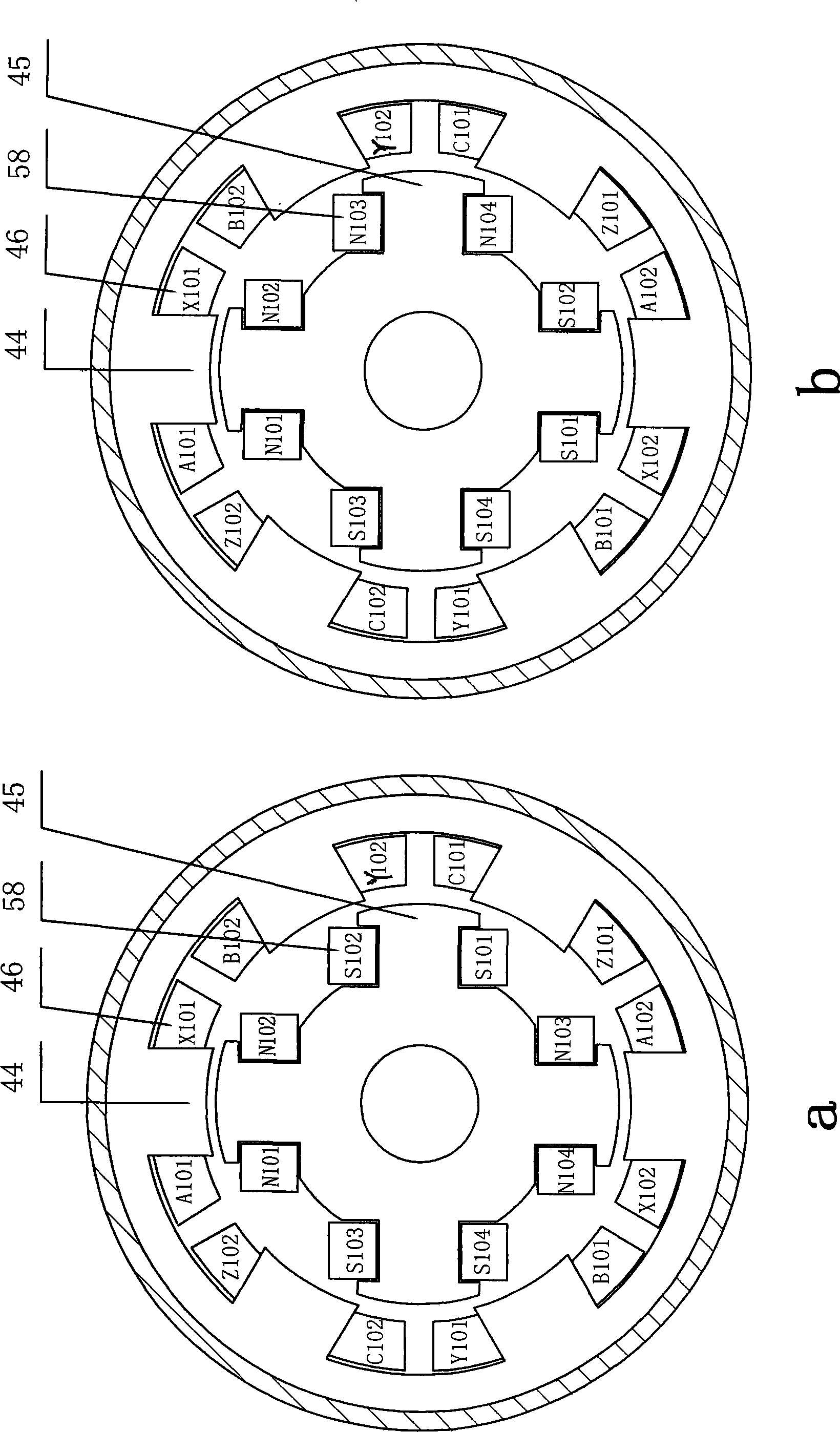
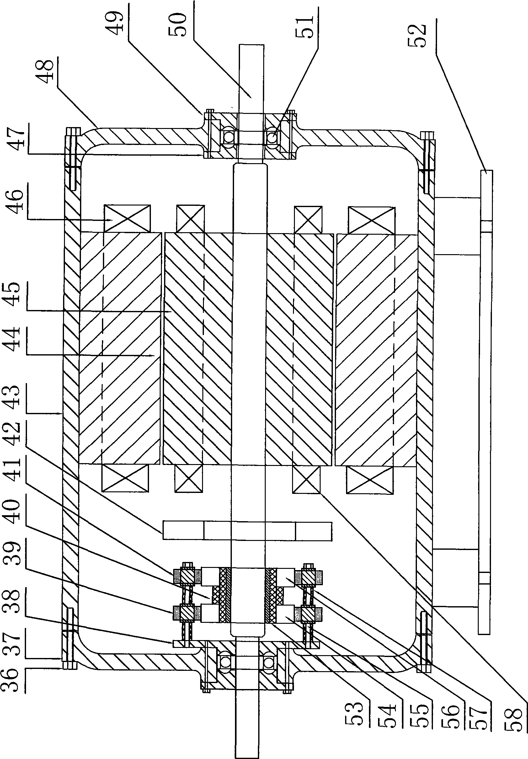
[0059] Embodiment 1 A switched reluctance motor generator (see figure 2 , 3 ), including a stator 44, a rotor 45, a rotor excitation device and an electronic sensor all laminated by silicon steel sheets into a salient pole structure, there is a concentrated armature winding 46 on the teeth of the stator 44, and the armature windings on the two teeth of the same phase of the winding 46 A phase is formed in series or in parallel, and a winding 58 is provided on the rotor 45 . The electronic sensor is mounted on the motor shaft 50 inside the motor.

[0060] The manufacturing installation of stator 44, rotor 45 can adopt figure 2 In 2a or 2b two ways. Among them, A101, B101, and C101 are the first ends of the stator S pole winding 46; A102, B102, and C102 are the first ends of the stator N pole winding 46; X101, Y101, and Z101 are the tail ends of the stator S pole winding 46; X102, Y102, and Z102 are the stator N N101 and N103 are the first ends of rotor N-pole winding 58; ...

Embodiment 2

[0069] Embodiment 2 A switched reluctance motor generator (see Figure 7 ), including a stator 44, a rotor 45, a rotor excitation device and a mechanical drive device (the application number is 200710194659.5), all of which are laminated by silicon steel sheets into a salient pole structure. There are concentrated armature windings 46 on the teeth of the stator 44, and the windings with the same phase The armature windings on the two teeth are connected in series or in parallel to form a phase, and the rotor 45 is provided with a winding 58 . The mechanical drive is mounted on the motor shaft 50 outside the motor.

[0070] The manufacture and installation of stator 44 and rotor 45 are the same as in embodiment 1.

[0071] The rotor excitation device is the same as that in Embodiment 1.

[0072] Mechanical drive device (for details, please refer to the "Mechanical Drive Device of Switched Reluctance Motor" manual, but the label number this time is different from the last one,...


PUM


Abstract

The present invention relates to a switch reluctance motor electricity generator, which comprises stator, rotor and driving device in salient pole structure pressure-superposed by silicon steel sheet, wherein tooth of the stator is provided with centralized armature winding; the armature winding are connected in series or in parallel to constitute a phase on two tooth of same windings phase, characterized in that the rotor is provided with windings. The driving device of the electricity generator can adopt either electronic sensor or mechanical driving device or combining both. The present invention breaks adding exciter winding on electric machine rotor in normal way, which enhances performance and efficiency of power generation.

Description

technical field [0001] The invention relates to the field of motors, in particular to a switched reluctance motor generator. Background technique [0002] The switched reluctance motor is a motor with a double salient pole structure. The salient poles of the stator and rotor are laminated with ordinary silicon steel sheets. The rotor has neither winding nor permanent magnet, and the stator pole is wound with a concentrated winding. The number can be divided into single-phase, two-phase, three-phase, four-phase and multi-phase switched reluctance motors, among which the three-phase 6 / 4 structure and the four-phase 8 / 6 structure are the majority. The switched reluctance motor has the advantages of simple structure, easy manufacture, reliable operation, not easy to damage, easy speed regulation, high power factor, high efficiency, large starting torque, small starting current, strong overload capacity, and can start with heavy loads. Its high-speed constant power range is wide...

Claims


Application Information

Patent Timeline
Patent Type & Authority Applications(China)
IPC IPC(8): H02K29/00H02K7/20
Inventor 张世清
Owner 张世清
Why Eureka
Try Eureka