
DC to DC transformer and control method for reducing overshooting phenomenon

A DC-to-DC converter technology, applied in the direction of converting DC power input to DC power output, control/regulation systems, output power conversion devices, etc., can solve problems such as poor stability of DC-DC converters

Active Publication Date: 2009-07-15
ASUSTEK COMPUTER INC +1
View PDF2 Cites 14 Cited by
  • Summary
  • Abstract
  • Description
  • Claims
  • Application Information

AI Technical Summary

Problems solved by technology

Furthermore, the PWM signal of this patent will constantly change, so the stability of the entire DC-to-DC converter will deteriorate

Method used


Image

  • DC to DC transformer and control method for reducing overshooting phenomenon
  • DC to DC transformer and control method for reducing overshooting phenomenon
  • DC to DC transformer and control method for reducing overshooting phenomenon

Examples


Embodiment Construction

[0051] Please refer to Figure 7 , which is a flow chart of the control method of the DC-to-DC converter of the present invention. First, continuously monitor the DC output voltage (step S10). When the DC output voltage is less than the first threshold voltage (step S12), then jump to step S10; otherwise, when the DC output voltage is greater than the first threshold voltage (step S12), then increase the frequency of the PWM signal, that is, Increase from a first frequency to a second frequency (step S14). Next, continuously monitor the DC output voltage (step S16). When the DC output voltage is greater than the first threshold voltage (step S18), then jump to step S16; otherwise, when the DC output voltage is less than the first threshold voltage (step S18), then restore the frequency of the original PWM signal, that is , decrease from the second frequency to the first frequency (step S20), and skip to (step S10).

[0052] According to an embodiment of the present inventi...


PUM


Abstract

The present invention discloses a DC to DC converter, which comprises: a control circuit used for receiving and comparing DC output pressure, and outputs pulse wave width modulation signal of the first frequency when the DC output pressure no more than the first threshold voltage, and outputs pulse wave width modulation signal of the second frequency when the DC output pressure more than the first threshold voltage and the second frequency higher than the first frequency; a gate drive circuit used for receiving pulse wave width modulation signal and converting it into the first drive signal and the second drive signal; and a power stage circuit used for converting DC input pressure into DC output pressure according to the first drive signal and the second drive signal.

Description

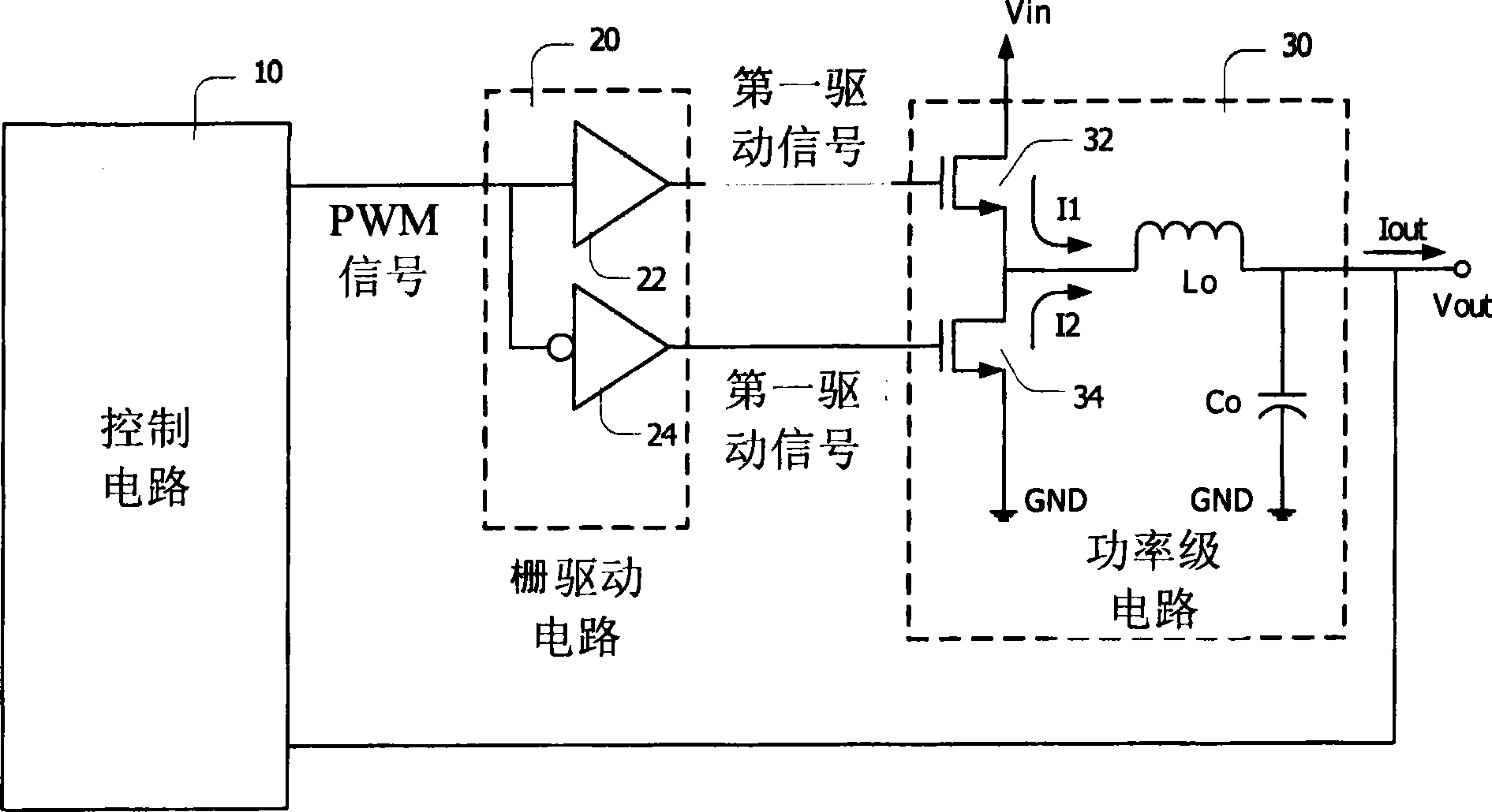
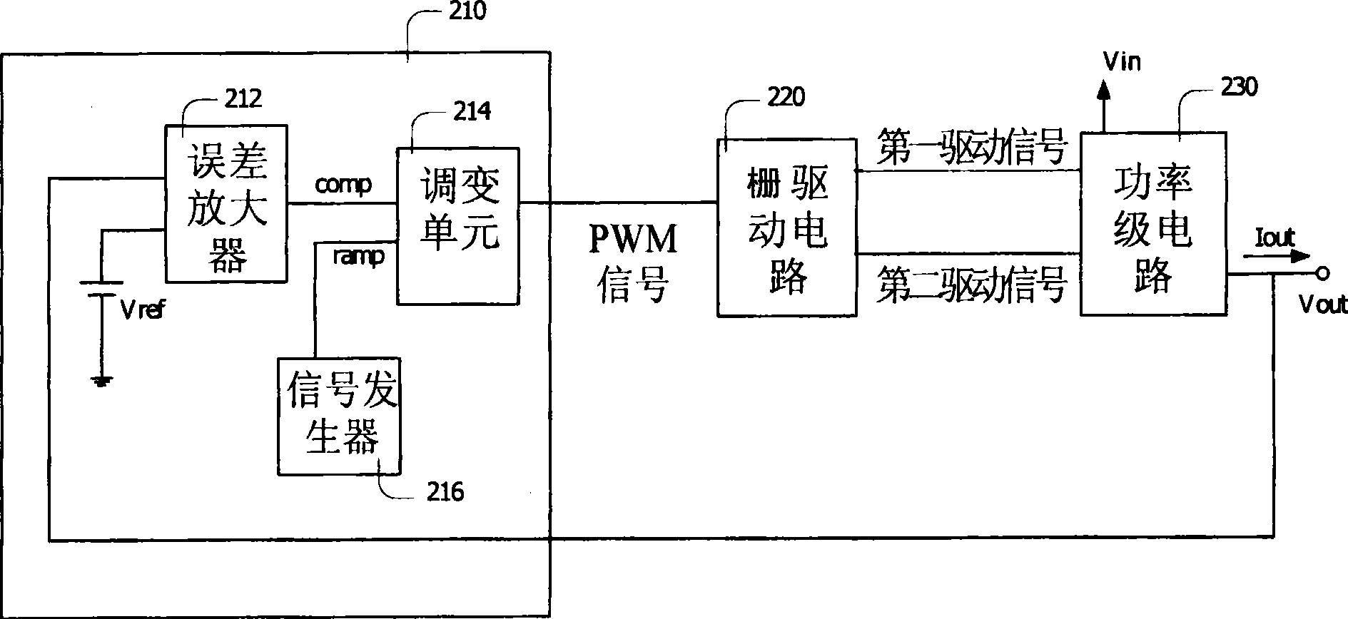
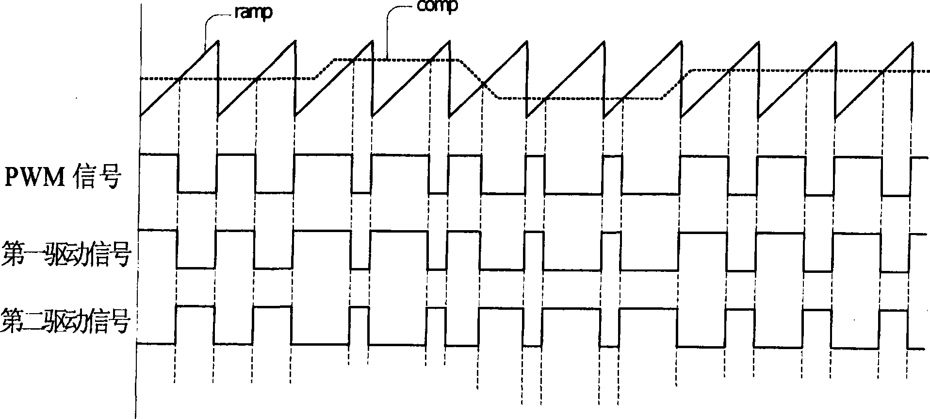
technical field [0001] The present invention relates to a DC-to-DC converter, and more particularly to a DC-to-DC converter and a control method for reducing overshoot. Background technique [0002] As is well known, a DC-to-DC converter (DC-to-DC converter) can convert a DC input voltage (DC input voltage) into a DC output voltage (DC output voltage) of different magnitudes. [0003] Please refer to figure 1 , which is a schematic diagram of a known DC-to-DC converter. The DC-to-DC converter includes a control circuit 10 , a gate driver 20 , and a power stage 30 . Generally speaking, the control circuit 10 can receive the DC output voltage (Vout) generated by the power stage circuit 30, and generate a corresponding pulse width modulation signal (pulse width modulation signal, hereinafter) according to the change of the DC output voltage (Vout). Referred to as PWM signal). Moreover, the gate drive circuit 20 receives the PWM signal and converts it into a first drive sign...

Claims


Application Information

Patent Timeline
Patent Type & Authority Applications(China)
IPC IPC(8): H02M3/135H02M1/14
Inventor 韩伟梁清吉刘涛
Owner ASUSTEK COMPUTER INC
Learn More