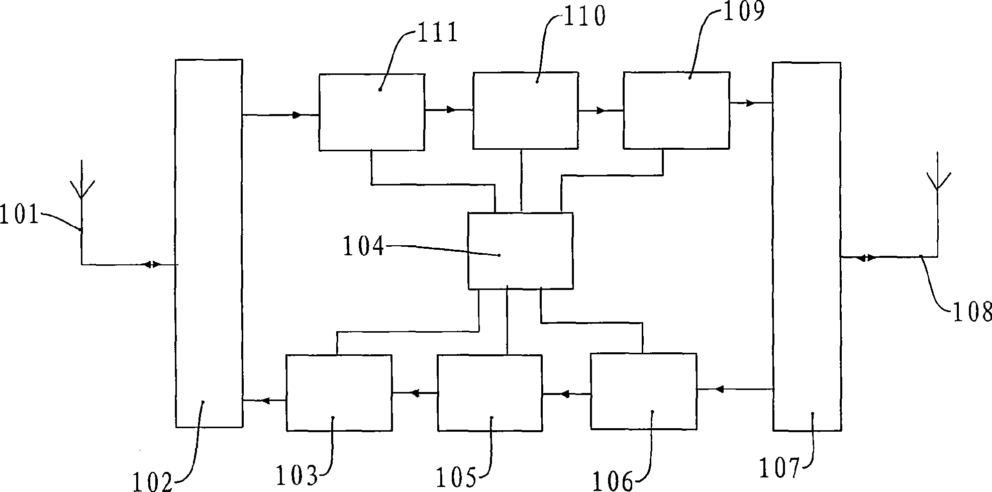
Healing method for straight-forward station self-excitation

A repeater, self-excitation technology, applied in electrical components, wireless communication, network planning, etc., can solve problems such as affecting user calls, reducing the work gain of the repeater, and failing to completely solve the self-excitation problem of the repeater. achieve short-lasting effects

Inactive Publication Date: 2009-07-15
珠海银邮光电技术发展股份有限公司
1 Cites 4 Cited by

AI-Extracted Technical Summary

Problems solved by technology

The disadvantage of this solution is that although the repeater is no longer self-excited, the working gain of the repeater is reduced, and the radiation ra...

Abstract

The invention relates to the performance optimization of a repeater station device in a communication field, particularly relating to a self-excited cure method for the repeater station device. The self-excited cure method for the repeater station comprises the following four processes: 1) a process from the production of self-excitation to a stable state; 2) a process that the stable state probes a normal state; 3) a self-excited probing process under the normal state; 4) a self-excited alarming synthesis reporting treatment process. According to a plurality of self-excited phenomena, the method of the invention can effectively cure, even though can not cure, the phenomena can be reported to a monitor center through the process 4) and treated by other methods.

Application Domain

Network planning

Technology Topic

EngineeringSelf excited +3

Image

  • Healing method for straight-forward station self-excitation

Examples

  • Experimental program(1)

Example Embodiment

[0026] The self-excitation and self-healing method of the repeater of the present invention includes the following processes:
[0027] 1) The process from self-excitation to a stable state;
[0028] 2) The process of steady state testing of normal state;
[0029] 3) Self-excited probing process under normal conditions;
[0030] 4) The processing process of self-excited alarm synthesis report.
[0031] For ease of explanation, the following parameters are explained as follows:
[0032] a. MAX_ATT: the maximum attenuation value of the repeater;
[0033] b. OMT_ATT: the attenuation value set by the local monitoring center or remote monitoring center;
[0034] c. BST_ATT: Temporary attenuation value used in the self-healing process, the initial value is 9dB;
[0035] Detailed description of the four sub-processes:
[0036] 1) The process from self-excitation to a stable state:
[0037] a. When the monitoring unit detects that there is still a self-excited alarm after the confirmation process of 3 minutes, the self-healing function is turned on. The self-excitation detection method is consistent with the existing method, that is, the monitoring unit CPU compares the detected uplink/downlink output power with the preset own threshold. When it detects that the uplink/downlink output power exceeds the self-excitation threshold, there is Self-excited. The three-minute confirmation process means that when the monitoring unit detects that the device has self-excited for 3 consecutive minutes, a self-excitation alarm is formed.
[0038] b. Decrease the gain (attenuation) by 3dB for the first time, and check whether it is still self-excited. If it is still self-excited, continue to attenuate 3dB, and continue this process until no self-excitation occurs. But when the total attenuation value (BST_ATT) in this sub-process is greater than or equal to (MAX_ATT-OMT_ATT), but still self-excited, proceed to process 4). This step is mainly to find the self-excitation depth. In this embodiment, we choose to reduce the gain by 3dB each time. Of course, other values ​​can also be used for testing. The testing method can also be to reduce the larger gain value, and then gradually increase the gain. In addition, the value of gain can be different each time.
[0039] c. After completing the above process b, if the radio frequency module does not have a self-excited alarm, it enters a stable state and enters process 2).
[0040] 2) The process of steady state testing of normal state:
[0041] a. After entering the stable state, if self-excitation is detected again, proceed directly to process 4).
[0042] b. After entering the stable state, if no self-excitation is detected, it will enter the process of returning to the normal state. The process of returning to the normal state is to gradually increase the gain by 1dB each time (of course, it can also increase other 2dB or more each time). If there is no self-excitation in the process of increasing the gain, the gain is increased until the repeater In the original normal state, add 3dB to the gain [that is, test to the attenuation value of the device (OMT_ATT-3dB), but when OMT_ATT<3dB, the final target value is 0dB, that is, the above value is no longer added to 3], Then reduce the gain by 3dB, that is, the device attenuation is restored to OMT_ATT, return to the normal state, and reset the number of attempts to return to the normal state to zero, and enter process 3); if there is self-excitation during the process of increasing the gain, the gain is reduced once To the position of the stable state, proceed to the next process of trying to restore the normal state, and increase the number of attempts to restore the normal state by one. The initial value of the number of attempts to restore the normal state is zero. If the number of attempts to restore the normal state reaches Preset times, enter process 4); in order to avoid frequent actions, it is necessary to set the waiting time. The waiting time for the first return to normal state is 10 minutes, the second 30 minutes, and the third time is 2 hours. If it successfully returns to the normal state without self-excitation, the number of attempts will be reset to zero. The waiting time here can be selected flexibly. For example, the waiting time for the first time can be 5-15 minutes, the second time is 20-40 minutes, and the third time afterwards it is 1.5-3 hours.
[0043] 3) The self-excited trial process under normal conditions:
[0044] a. The goal of self-excited probing is 3dB greater than the existing gain.
[0045] b. If self-excitation occurs, it will attenuate immediately (OMT_ATT+BST_ATT) and enter the process of returning to the normal state, but the waiting time for each return to the normal state is 1.5-3 hours, preferably 2 hours.
[0046] 4) Processing process of self-excited alarm synthesis report:
[0047] a. Generation of equipment self-excitation alarm: the equipment detects the self-excitation of the radio frequency module and enters the steady state process after self-excitation generation, and the process of steady state testing the normal state, will cause the equipment to generate self-excitation alarm. Each alarm is judged for 3 minutes. The RF modules mentioned in this article include duplexers, uplink/downlink power amplifiers, radio frequency digital attenuators and uplink/downlink low noise amplifiers.
[0048] b. Releasing of the equipment self-excitation alarm: no self-excitation is generated by the radio frequency module, and the equipment is in a normal state and satisfies no self-excitation alarm for a continuous period of 3 minutes.
[0049]c. The self-excitation alarm reported by the device needs to be combined with the uplink/downlink self-excitation alarm, that is, an alarm is reported on one channel, and the alarm can be removed after both channels are recovered. The self-excitation alarm is synthesized and reported to the monitoring center outside the repeater, and then other methods are used to process the self-excitation of the repeater.
[0050] Of course, the present invention can also have other variations on the self-excitation cure method of repeater equipment. In short, obvious changes made based on the hints of the above examples, as well as other changes that do not deviate from the essence of the present invention, should be included in the scope of the claims.

PUM

no PUM

Description & Claims & Application Information

We can also present the details of the Description, Claims and Application information to help users get a comprehensive understanding of the technical details of the patent, such as background art, summary of invention, brief description of drawings, description of embodiments, and other original content. On the other hand, users can also determine the specific scope of protection of the technology through the list of claims; as well as understand the changes in the life cycle of the technology with the presentation of the patent timeline. Login to view more.

Similar technology patents

Freezing of biological material

PendingUS20220095609A1short durationreduce duration
Owner:SCI GRP AS

Driving method and device for improving image display quality

PendingCN111312142Ashort durationshorten sending time
Owner:FUJIAN HUAJIACAI CO LTD

Falling type vending machine

PendingCN114220218Ashort durationrun smoothly
Owner:成都中康大成环保科技有限公司

Arc suppression and overvoltage suppression system

InactiveCN108879647Ashort duration
Owner:安徽亚辉电气自动化有限公司

Push-button vessel wall mri with 3d scout scan

ActiveCN105683772Ashort duration
Owner:KONINKLJIJKE PHILIPS NV +1

Classification and recommendation of technical efficacy words

  • short duration

Method for transferring a sheet between two conveyors

InactiveUS20160152045A1short durationreduce stiffness
Owner:OCE TECH

Virtual prop control method and device, computer equipment and storage medium

ActiveCN112169325AImprove the effectshort duration
Owner:TENCENT TECH (SHENZHEN) CO LTD

Lightning protection circuit and lightning protection method for direct-current power supply port of communication equipment

InactiveCN104253426AHigh lightning protection efficiencyshort duration
Owner:FENGHUO COMM SCI & TECH CO LTD
Why Eureka
Try Eureka