Ballast water treatment plant having filter, disinfection, instrumentation and control unit

A water treatment device and technology of a treatment device, applied in water treatment devices, filtration treatment, water/sewage treatment, etc., can solve problems such as uncertified ballast water treatment

Inactive Publication Date: 2009-07-15
RWO
View PDF13 Cites 21 Cited by
  • Summary
  • Abstract
  • Description
  • Claims
  • Application Information

AI Technical Summary

Problems solved by technology

However, this does not prove...

Method used


Image

  • Ballast water treatment plant having filter, disinfection, instrumentation and control unit

Examples


Embodiment Construction

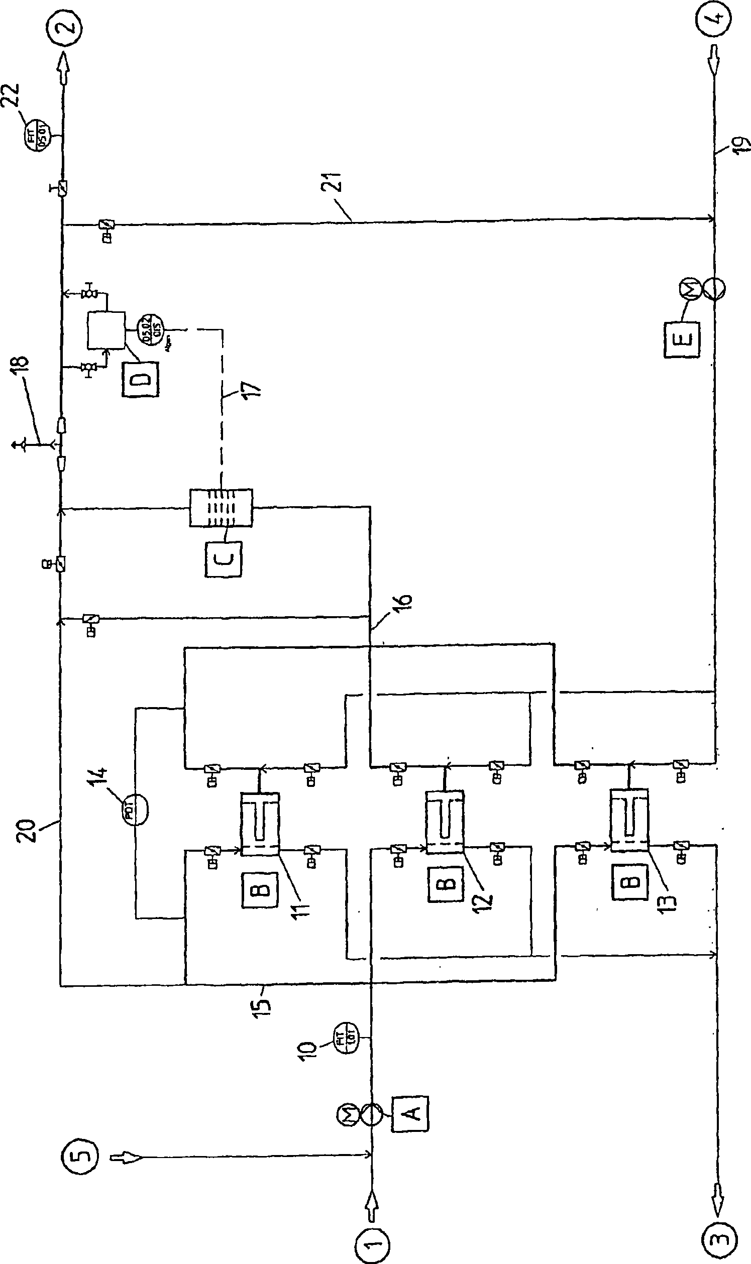
[0101] Said basis figure 1 The water treatment unit allows various operating modes, which are explained in detail below. The functional description of the processing means is divided as follows:

[0102] 1. Reception of ballast water

[0103] 2. Back flushing of the filter during ballast water reception (internal cleaning of the filter)

[0104] 3. Filter cleaning after ballast water reception

[0105] 4. Discharge ballast water

[0106] 5. Bypass emergency operation

[0107] Case 1: Reception of ballast water

[0108] The treatment steps of the device consist of a filtration process in the filter unit B with filters 11 , 12 , 13 in the form of disc filters and a disinfection process C based on the principle of electrolysis.

[0109]The filter unit B consists of three filters 11 , 12 , 13 connected in parallel in the form of disc filters. Disc filters form the filter area by means of plastic discs pressed one above the other. These plastic discs have grooves on the upp...


PUM


Abstract

Water treatment plant, in particular ballast water treatment plant, for removing sediments and/or removing and/or destroying living organisms, which has at least one filter unit (B) and at least one disinfection unit (C), wherein the plant has a detection unit (D) by means of which the number of living organisms of a presettable size per unit volume of water can be determined, and in that the plant has a control unit, by means of which the disinfection unit (C) can be controlled as a function of the number of living organisms which has been determined.

Description

technical field [0001] The invention relates to a water treatment plant, in particular a ballast water treatment plant, for removing sediment and / or for removing and / or killing living organisms, said water treatment plant having at least one filter unit and at least one disinfection unit unit. Background technique [0002] Ballast water carrying invasive organisms is one of the greatest threats to the world's oceans. In order to stabilize the situation, the ship must receive ballast water if it is unloaded or not fully loaded. Ships carry sediment and organisms, such as algae, in ballast water and release said organisms upon discharge in the arrival port / arrival area. Depending on the navigation route of the ship, these organisms do not occur naturally in the area, these organisms may come to fruition as invasive organisms under suitable living conditions and lack of natural enemies, and this leads to significant ecological aspects, Economic and health hazards. [0003] ...

Claims


Application Information

Patent Timeline
IPC IPC(8): C02F1/38C02F1/467
CPCC02F1/008C02F2301/043C02F1/20C02F1/4674C02F2209/29C02F2209/03C02F2209/40B63J4/004C02F1/001C02F2209/008C02F2103/008C02F1/38C02F1/44C02F1/467B01D61/00C02F2103/02
Inventor A·考恩穆勒H·沃勒
Owner RWO
Why Eureka
Try Eureka