Wave-propagation based estimation of coil sensitivities

A technology of wave propagation and sensitivity map, which is applied in the field of parallel imaging technology, can solve the problems of not considering the geometric shape of the coil, inaccuracy, etc., and achieve the effect of improving the combination of coil signals, reducing artifacts, and accurately unfolding

Inactive Publication Date: 2009-07-15
KONINKLIJKE PHILIPS ELECTRONICS NV
View PDF0 Cites 4 Cited by
  • Summary
  • Abstract
  • Description
  • Claims
  • Application Information

AI Technical Summary

Problems solved by technology

However, because such interpolation techniques do not take coil geometry into account, they also suffer from inaccuracies...

Method used


Image

  • Wave-propagation based estimation of coil sensitivities
  • Wave-propagation based estimation of coil sensitivities
  • Wave-propagation based estimation of coil sensitivities

Examples


Embodiment Construction

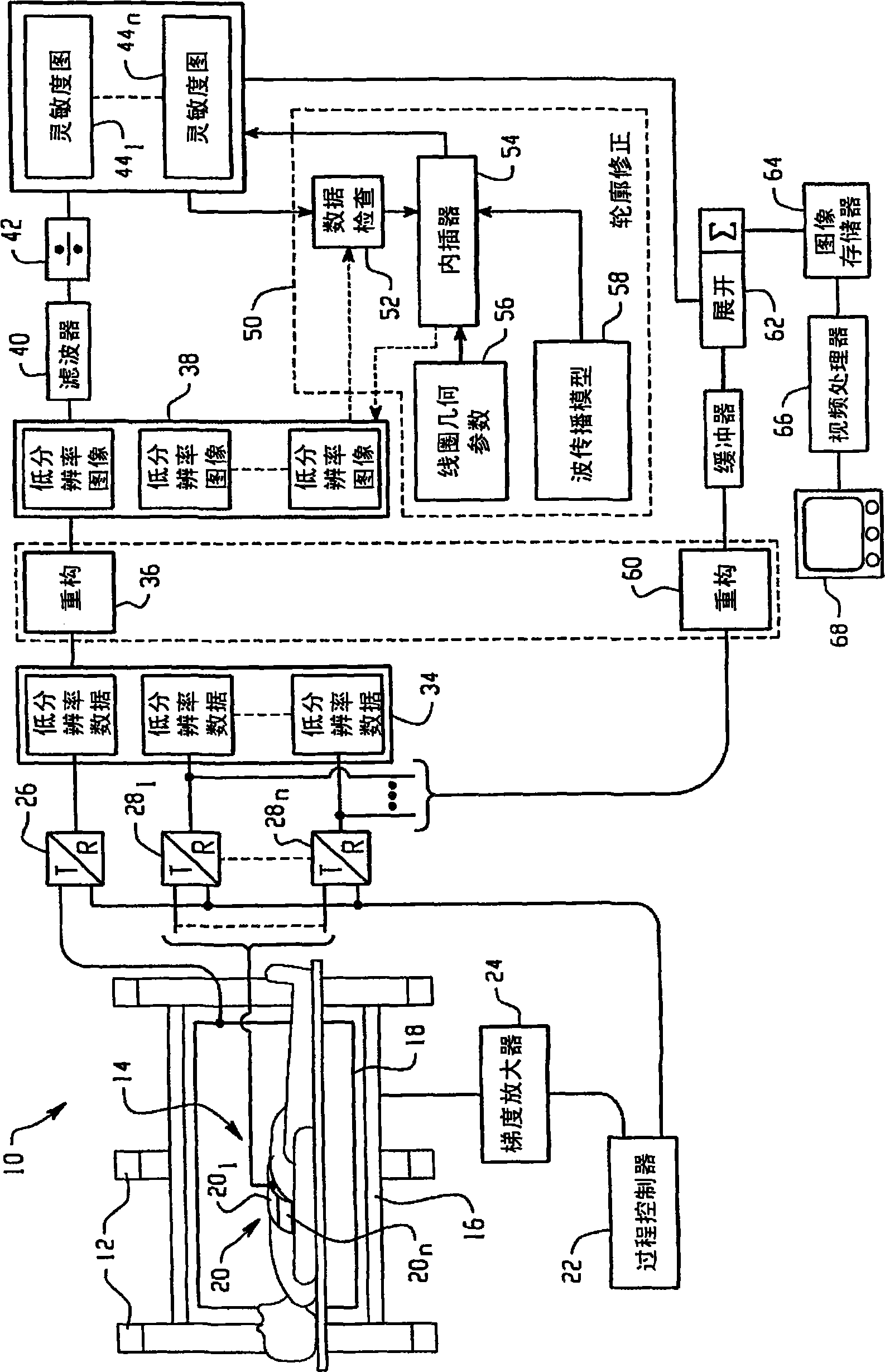
[0023] refer to figure 1 , the MRI imaging system 10 includes one or more main field coils 12 that generate a main magnetic field or B across an imaging region 14 0 magnetic field. The main field coils can be superconducting, resistive, permanent magnets, etc. Gradient coil 16 is applied across the B 0 Field gradient magnetic field G x , G y , G z , to provide space, frequency, and phase encoding. An integral transmit / receive coil 18 transmits resonance excitation and operating RF pulses into the imaging zone 14 and receives magnetic resonance signals from the imaging zone.

[0024] Locally parallel imaging coils 20 are arranged adjacent to an object in imaging region 14 . The parallel imaging coil comprises a plurality of elements or loops, working individually or in small groups, hereinafter referred to as coil elements 20 1 , 20 2 ,...20 n , used to simultaneously generate imaging data from different subregions of k-space.

[0025] A sequence controller 22 contro...


PUM


Abstract

Low resolution image data from a whole-body coil (18) and each coil element (201, 202, 20n) of a parallel imaging coil are received in a memory or buffer (34). A reconstruction processor (36) reconstructs the low resolution whole-body coil data and the low resolution data from each of the coil elements into corresponding low resolution images (38). The low resolution from each coil element is divided (42) by the low resolution image from the whole-body coil to generate a corresponding sensitivity map (441, 442, 44n) for each of the coil elements. In areas where the low resolution body coil image has near-zero values or in areas where the values in the body coil or receive coil images are changing very rapidly, the sensitivity maps have defects. A sensitivity map or correction circuit or algorithm (50) determines regions of the sensitivity maps which are defective and interpolates/extrapolates adjacent portions of the sensitivity maps in accordance with (a) a coil geometry map (56) and (b) a wave-propagation model (58) to correct the defective regions, to propagate them into the outer regions of the field of view or to fully replace the measured sensitivity map and create a corrected sensitivity map for each coil element.

Description

technical field [0001] This application relates to parallel imaging techniques. It has particular application to medical diagnostic imaging using the SENSE parallel imaging technique, and this application is described with specific reference to medical diagnostic imaging. However, it will be appreciated that the present application may also be used for other parallel imaging techniques and for other imaging besides medical diagnostic purposes. Background technique [0002] Various parallel imaging techniques are known to produce magnetic resonance images more quickly. These parallel imaging techniques include SENSE, SMASH, etc. During magnetic resonance imaging, different receive coils or sets of receive coils simultaneously sample different parts of k-space. In reconstructing the diagnostic image, the data from each coil (or set of coils) is transformed or "unfolded" according to its sensitivity. The accuracy of the final image depends on accurately determining the coil...

Claims


Application Information

Patent Timeline
IPC IPC(8): G01R33/3415
CPCG01R33/5611G01R33/3415
Inventor R·温克尔曼P·博尔纳特
Owner KONINKLIJKE PHILIPS ELECTRONICS NV
Why Eureka
Try Eureka