Microshock fine cutting surgical knife handle

A scalpel handle and micro-vibration technology, applied in the direction of dissection instruments, etc., can solve the problems of skin wrinkling, the blade is difficult to cut accurately and efficiently, and it is not easy to cut accurately, so as to achieve the effect of efficient cutting

Inactive Publication Date: 2009-07-22
张毅昆
View PDF0 Cites 8 Cited by
  • Summary
  • Abstract
  • Description
  • Claims
  • Application Information

AI Technical Summary

Problems solved by technology

There are the following disadvantages when doing fine cutting: 1. When the surgical field is very small, the blade is not easy to complete precise and efficient cutting; 2. When the tissue is soft and the tissue is not allowed to be pulled very tightly, the blade is very Difficult to cut accurately and efficiently
For example, in double eyelid surgery by incision method, pulling the skin too tightly during incision may cause the incision to not be cut accurately according to the designed line; while under the condition of not tensioning the skin, the downward longitudinal pressure of the blade and the force toward the skin plane The back and forth cutting force can cause the skin to wrinkle and make it difficult to cut accurately

Method used


Image

  • Microshock fine cutting surgical knife handle
  • Microshock fine cutting surgical knife handle
  • Microshock fine cutting surgical knife handle

Examples


Embodiment 1

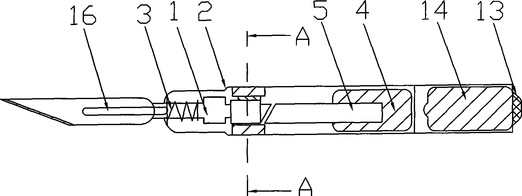
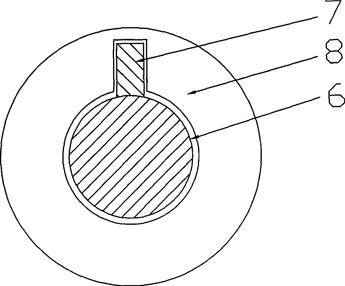
[0029] Such as figure 1 , figure 2 with Picture 9 As shown, the present invention includes a blade connector 1, a housing 2, a spring 3, a motor 4, a motor shaft 5, a battery 14, a switch and an external power source 13, and a transmission device between the blade connector 1 and the motor shaft 5. The motor 4 and the power supply device are located at the end of the inner cavity of the housing 2, the spring 3 penetrates and is connected to the blade connector 1, and the other end is connected to the front end of the inner cavity of the housing 2; The blade connector 1 and the blade are connected by a slot joint 16. The cross-section of the slot coupling member 16 is an I-shaped slot, and the card slot cooperates with the card hole on the blade so that the blade is fixedly connected to the slot coupling member 16. The transmission device is a movement direction conversion member, the movement direction conversion member includes a transmission shaft 6, a flat key 7 and a fixing ...

Embodiment 2

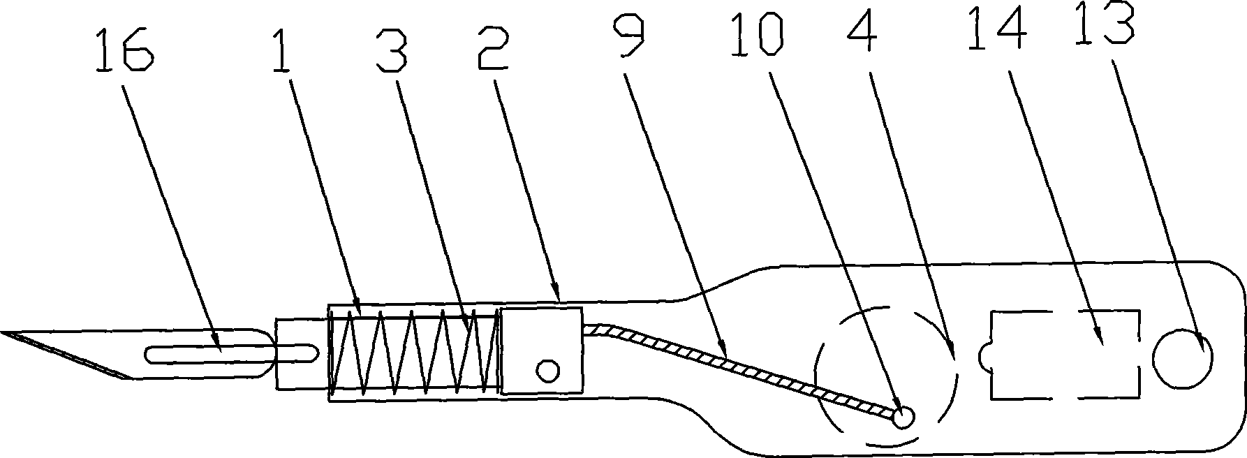
[0031] Such as image 3 with Picture 9 As shown, the structure of the transmission device in this embodiment is different from that in the first embodiment. The transmission device may also be a bending link 9; one side of the motor shaft 5 is welded with a secondary shaft 10 in parallel; one end of the bending link 9 is rotatably connected to the blade connector 1, and the other end is rotated Connected to the secondary shaft 10; when the secondary shaft 10 rotates under the action of the motor 4, it drives the bending link 9 to swing, and the bending link 9 then drives the blade connector 1 to make a longitudinal reciprocating motion.

Embodiment 3

[0033] Such as Figure 4 , Figure 5 with Picture 9 As shown, the transmission device in this embodiment is a connecting rod 11, and other structures remain unchanged; a side shaft 10 is welded parallel to the motor shaft 5, and the A end of the connecting rod 11 is connected to the blade connector 1 In a fixed connection, the B end has a circular hole with a diameter larger than that of the secondary shaft 10, and the secondary shaft 10 is sleeved in the circular hole. When the secondary shaft 10 swings, under the reaction force of the spring 3, the connecting rod 11 is reciprocated in the A and B directions; because the connecting rod 11 and the blade connector 1 are fixedly connected, the connecting rod 11 The reciprocating motion can be directly transmitted to the blade connector 1.


PUM


Abstract

The invention discloses a scalpel handle, which aims to provide a microseismic precision cutting scalpel handle capable of accurately and efficiently cutting. Besides a blade connecting piece (1) and a shell (2), the microseismic precision cutting scalpel handle also comprises a spring (3), a motor (4), a motor shaft (5), a power device and a transmission device between the blade connecting piece (1) and the motor shaft (5), wherein the motor (4) allows the blade connecting piece (1) to get longitudinal reciprocating motion through the transmission device. The scalpel handle is widely applied to the field of medical operations.

Description

Technical field [0001] The invention relates to a micro-vibration fine cutting scalpel handle. Background technique [0002] The scalpel handle currently used in clinical medicine is only used to fix the blade for holding. There are the following shortcomings in fine cutting: 1. When the surgical field is very small, the blade is not easy to complete accurate and efficient cutting; 2. When the tissue is soft and does not allow the tissue to be pulled tightly, the blade is very It is difficult to cut accurately and efficiently. For example, during double eyelid surgery by incision, pulling the skin too tightly during incision may cause the incision to not be cut accurately according to the design line; and without straining the skin, the downward longitudinal pressure of the blade and the plane of the skin Cutting force back and forth can cause the skin to wrinkle and make it difficult to cut accurately. Summary of the invention [0003] The technical problem to be solved by the ...

Claims


Application Information

Patent Timeline
Patent Type & Authority Applications(China)
IPC IPC(8): A61B17/3211
Inventor 张毅昆张悦
Owner 张毅昆
Why Eureka
Try Eureka