Double-functional manual biogas liquid residue discharge pump

A discharge pump, dual-function technology, applied in the field of manual biogas residue and biogas liquid discharge pump, can solve the problems of slow discharge speed, low discharge pressure, low discharge efficiency, etc. The effect of high pressure and high discharge efficiency

Inactive Publication Date: 2010-10-27
HARBIN DEGUANG NEW ENERGY
View PDF0 Cites 0 Cited by
  • Summary
  • Abstract
  • Description
  • Claims
  • Application Information

AI Technical Summary

Problems solved by technology

[0003] The purpose of the present invention is to solve the problems of low discharge pressure, slow discharge speed and low discharge efficiency in the existing biogas digester discharge pump, and to provide a dual-function manual biogas slurry discharge pump

Method used


Image

  • Double-functional manual biogas liquid residue discharge pump
  • Double-functional manual biogas liquid residue discharge pump

Examples


specific Embodiment approach 1

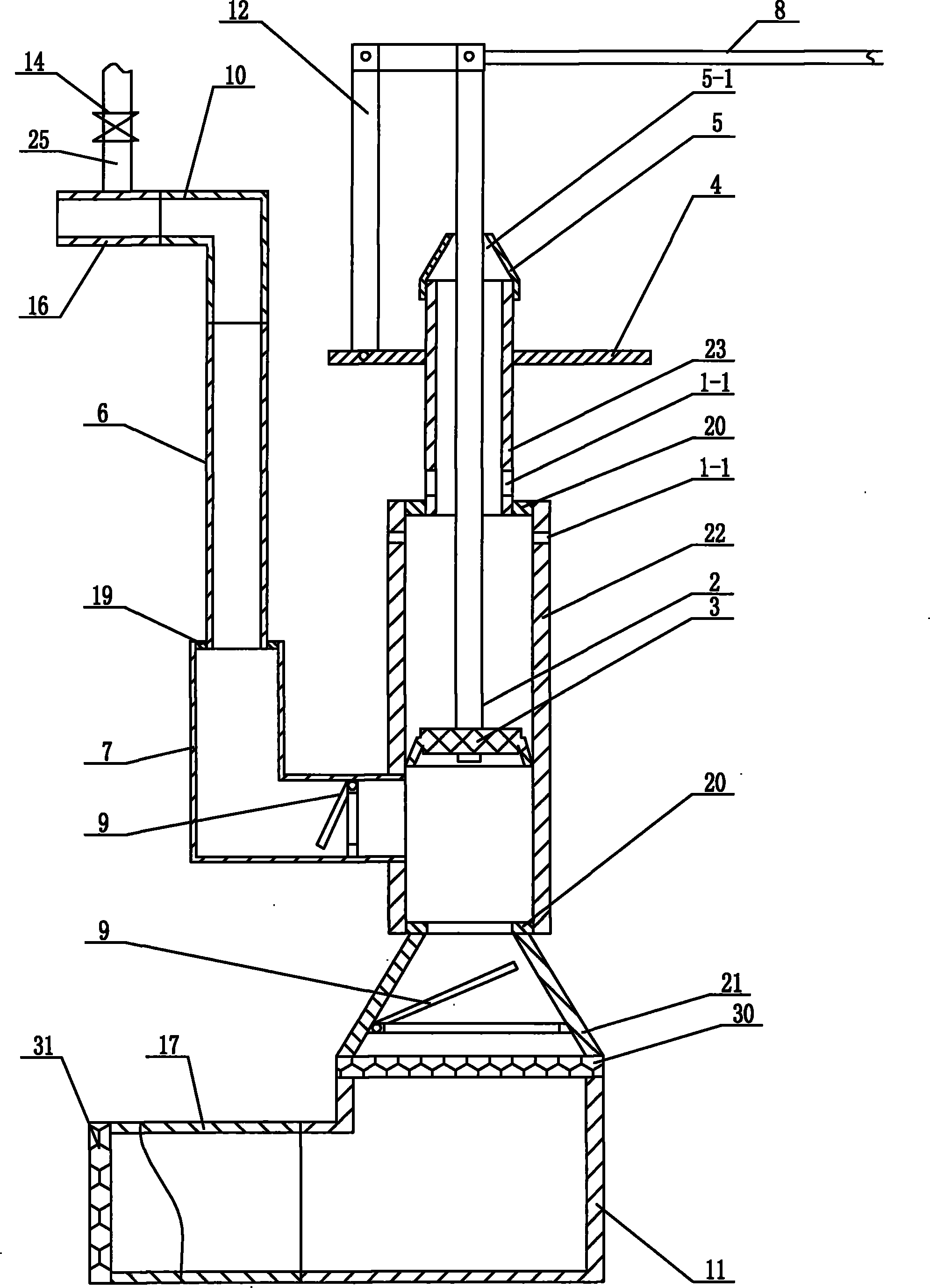
[0007] Specific implementation mode one: combine figure 1 Describe this embodiment, this embodiment includes a cylinder liner, a pull rod 2, a piston 3, a fastening plate 4, a reducer 5, a first elbow 7, a second elbow 10, a hand lever 8, two switches 9, Backwash pipe 6, hinge 12, valve 14, discharge pipe 16, second connector 19 and water inlet pipe 25, the large-diameter end of the reducer pipe 5 is threadedly connected to the upper end of the sheath support pipe 23 of the cylinder liner , the lower end of the pull rod 2 passes through the inner hole 5-1 of the reducer 5 and is installed in the piston working tube 22 of the cylinder liner, the lower end of the pull rod 2 is equipped with a piston 3, and the upper end of the pull rod 2 is connected with the hand pressure rod 8 One end of the hinge 12 and one end of the hinge 12 are hinged together, and the other end of the hinge 12 is hinged with the fastening plate 4, and the fastening plate 4 is fixed on the outer wall of th...

specific Embodiment approach 2

[0008] Specific implementation mode two: combination figure 1 To illustrate this embodiment, the cylinder liner of this embodiment is composed of a sheath support tube 23, a piston working tube 22, a connecting tube 21 and two first connectors 20, and the upper end surface and the lower end surface of the piston working tube 22 respectively pass through A first connecting piece 20 is connected with the lower end surface of the sheath support pipe 23 and the upper end surface of the connecting pipe 21 . So set, easy to install. Other compositions and connections are the same as in the first embodiment.

specific Embodiment approach 3

[0009] Specific implementation mode three: combination figure 1 The present embodiment will be described. The longitudinal section of the connecting pipe 21 of the cylinder liner of the present embodiment is trapezoidal. With such setting, the discharging speed is faster and the discharging efficiency is higher. Other compositions and connections are the same as those in the second embodiment.


PUM


Abstract

A manual double-function marsh dregs and marsh liquid discharging pump relates to a manual marsh dregs and marsh liquid discharging pump. The discharging pump helps solve the problems of small discharging pressure, slow discharging speed and low discharging efficiency and the like of the existing methane pool discharging pump. In the discharging pump, a big diameter end of a reducer is connected with an upper end screw thread of a sheathing support tube of a cylinder sleeve, the lower end of a draw bar passes an inner bore of the reducer to be arranged inside a piston work tube of the cylinder sleeve, a piston is arranged on the lower end surface of the draw bar, the upper end of the draw bar is hinged with one end of a hand pressing bar and one end of a hinged element, two switches are respectively positioned on the inner wall of a first elbow close to one end of the cylinder sleeve and the inner wall of a connecting tube of the cylinder sleeve, the lower end of a back-washing tube is connected with the upper end of the elbow by a second connecting part, and a discharging tube is connected with the back-washing tube by a second elbow. The discharging pump has the advantages of large discharging pressure, fast discharging speed and high discharging efficiency. The discharging pump also has the advantages of strong practicability, and being easy to dilute the marsh liquid, being easy for popularization and application and the like.

Description

technical field [0001] The invention relates to a manual biogas residue biogas slurry discharge pump. Background technique [0002] The discharge of traditional biogas digesters is carried by buckets or by electric sewage pumps and special vehicles, which is laborious, wastes energy, costs high, and the effect is not ideal, thus affecting the development of the biogas industry. In recent years, although various discharge pumps have been introduced or developed in various places, the development of the biogas industry has been restricted by problems such as low discharge pressure, slow discharge speed, and low discharge efficiency. Contents of the invention [0003] The purpose of the present invention is to solve the problems of low discharge pressure, slow discharge speed and low discharge efficiency in the existing biogas tank discharge pump, and further provide a dual-function manual biogas residue and biogas liquid discharge pump. [0004] The technical solution of th...

Claims


Application Information

Patent Timeline
Patent Type & Authority Patents(China)
IPC IPC(8): F04B15/02F04B9/14
Inventor 高德广
Owner HARBIN DEGUANG NEW ENERGY
Why Eureka
Try Eureka