Fuel cell system and method of operating fuel cell system

a fuel cell and system technology, applied in the field of fuel cell systems and methods of operating fuel cell systems, can solve the problems of the decrease in the flow rate of cathode off-gas as the diluting gas, and achieve the effect of rapid heating and reducing the pressure of the branched gas

Inactive Publication Date: 2014-01-02
HONDA MOTOR CO LTD
View PDF1 Cites 14 Cited by
  • Summary
  • Abstract
  • Description
  • Claims
  • Application Information

AI Technical Summary

Benefits of technology

[0037]With such a configuration, controlling an opening degree of the back pressure valve installed in the oxidant off-gas flow passage between the oxidant gas flow passage and the diluter can adjust the pressure of the oxidant gas in the oxidant gas flow passage of the fuel cell in accordance with, for example, a required power generation quantity.
[0038]In addition, because the branched gas flow passage is configured to be connected to the oxidant gas supplying flow passage more upstream than the back pressure valve, the pressure of the branched gas can be contr...

Problems solved by technology

However, in a case where the purge valve is opened at the end, just before, or just after the end of the OCV check process, if the low efficiency operation is started, in which the stoichiometric ra...

Method used


Image

  • Fuel cell system and method of operating fuel cell system
  • Fuel cell system and method of operating fuel cell system
  • Fuel cell system and method of operating fuel cell system

Examples


Embodiment Construction

[0050]With reference to FIGS. 1 to 8F, will be described an embodiment of the present invention.

>

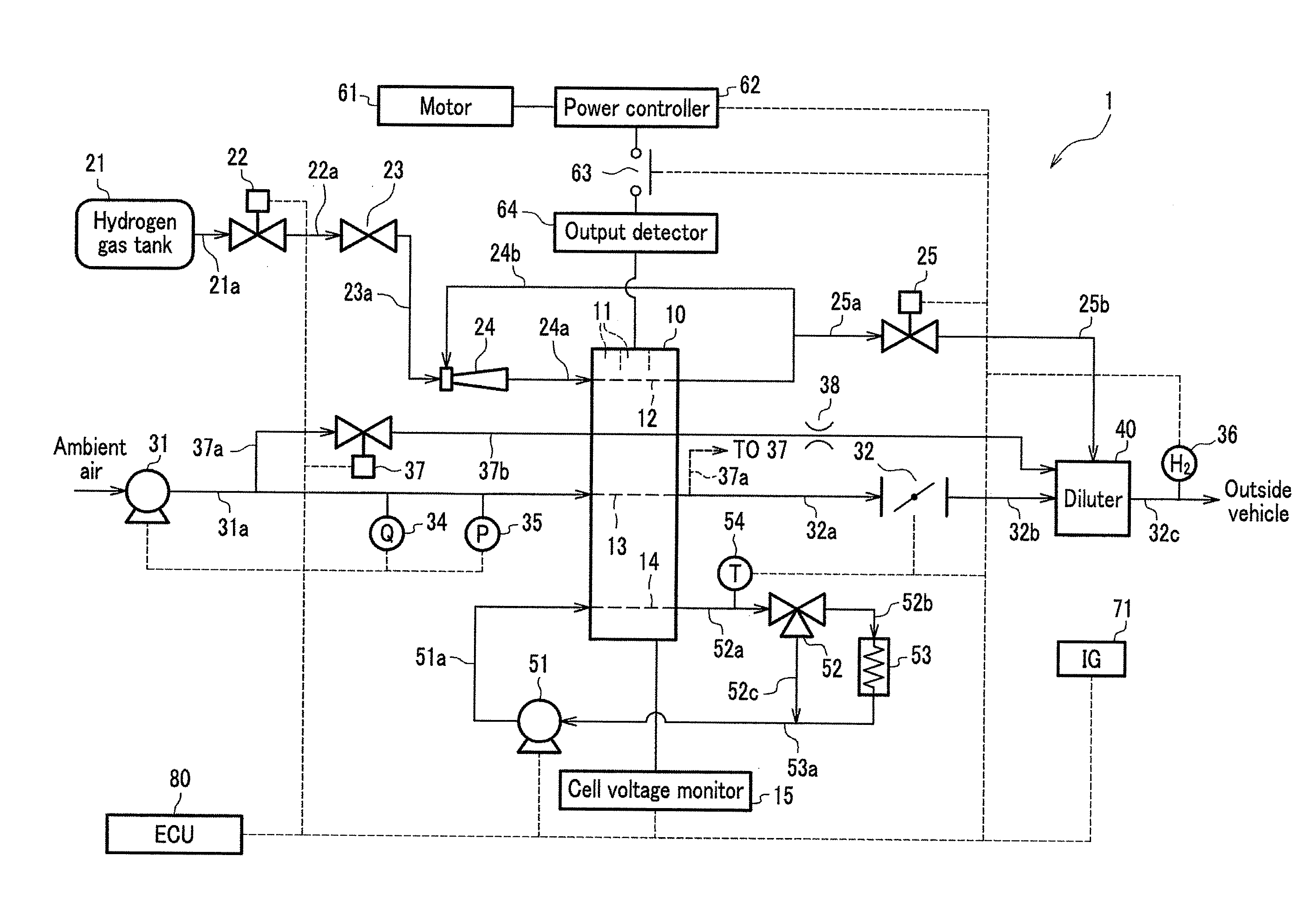
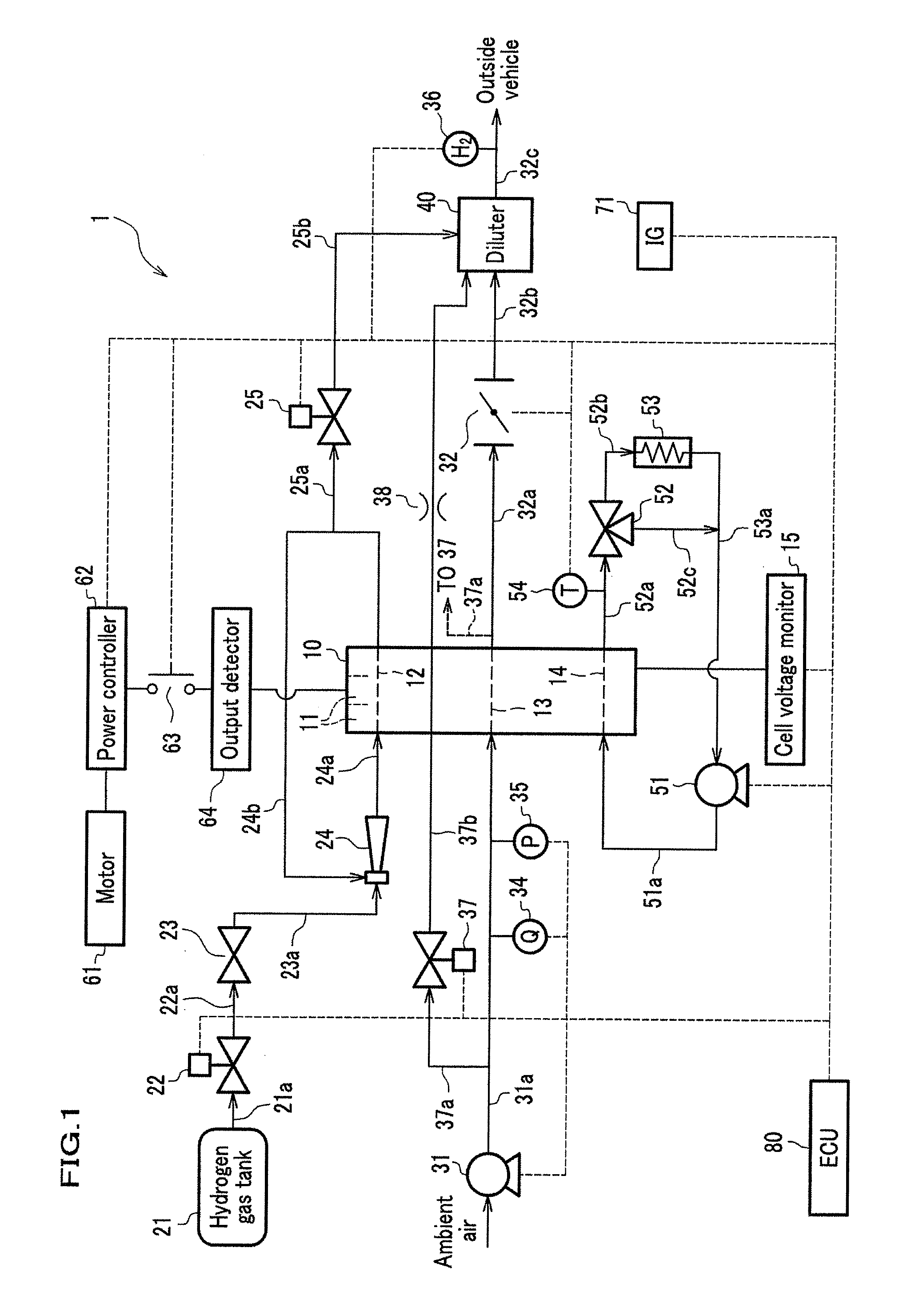
[0051]An fuel cell system 1 is mounted on a fuel cell vehicle (not shown) and includes an fuel cell stack 10 (fuel cell), a cell voltage monitor 15, an anode system for supplying and exhausting hydrogen gas (fuel gas, anode gas) to and from an anode of the fuel cell stack 10, a cathode system for supplying and exhausting the air (oxidant gas, cathode gas) to or from the cathode of the fuel cell stack 10, a coolant system for circulating a coolant through the fuel cell stack 10, a power control system for controlling a power (stack current, stack voltage) outputted by the fuel cell stack 10, and an ECU 80 (Electronic Control Unit, control unit) for electronically controlling these devices.

[0052]The fuel cell stack 10 is a stack formed by stacking a plurality (for example, 200 to 400) of single cells (fuel cells) 11 of solid polymer type, in which a plurality of the single cells (fuel cell...


PUM


Abstract

A fuel cell system includes: a fuel cell stack, a hydrogen gas tank, a compressor, an oxidant gas supplying flow passage, an oxidant off-gas discharge flow passage, a diluter for diluting an anode off-gas with a cathode off-gas, a branched gas flow passage through which a branched gas is directed to the diluter, a back pressure valve for controlling a pressure of branched gas, an OCV determining unit, and an I-V characteristic decreasing unit for starting power generation of the fuel cell stack and decreasing an I-V characteristic of the single cell by decreasing a stoichiometric ratios. In a low temperature start-up, the back pressure valve decreases a pressure of the branched gas introduced into the diluter when the I-V characteristic of the single cell is decreased by the I-V characteristic decreasing unit. An operation method of operating the fuel cell system is also disclosed.

Description

CROSS REFERENCE TO RELATED APPLICATION[0001]This application claims the foreign priority benefit under Title 35, United States Code, §119(a)-(d) of Japanese Patent Application No. 2012-144661, filed on Jun. 27, 2012 in the Japan Patent Office, the disclosure of which is herein incorporated by reference in its entirety.BACKGROUND OF THE INVENTION[0002]1. Field of the Invention[0003]The present invention relates to a fuel cell system and a method of operating a fuel cell system.[0004]2. Description of the Related Art[0005]In recent years, as a power source for a fuel cell vehicle, etc., a fuel cell has attracted notices, which generates electricity with supply of hydrogen gas (fuel gas) and an air including oxygen (oxidant gas). Such a fuel cell has a preferable temperature at which the fuel cell preferably generates electricity in accordance with a kind of a catalyst (Pt, etc.) for electrode reaction with hydrogen gas or the air (for example, 80 to 90 degrees centigrade in PEFC).[000...

Claims


Application Information

Patent Timeline
IPC IPC(8): H01M8/04
CPCH01M8/04544H01M8/04798H01M8/0488H01M8/0491H01M8/04955H01M8/0662H01M8/04268H01M8/04358H01M8/04559H01M8/04723H01M8/04753H01M8/04952Y02E60/50
Inventor WAKE, CHIHIROKAMIYAMA, TOMOHISAMATSUMOTO, YUJI
Owner HONDA MOTOR CO LTD
Why Eureka
Try Eureka