

Self-coupling continuously variable transmission
A continuously variable transmission and transmission technology, applied in the direction of fluid transmission, belt/chain/gear, mechanical equipment, etc., can solve the problems of CVT starting and low-speed driving, limited transmission power, and high manufacturing cost. The effect of good fuel saving, small size and low cost
- Summary
- Abstract
- Description
- Claims
- Application Information
AI Technical Summary
Problems solved by technology
Method used
Image

Examples
specific Embodiment approach 1
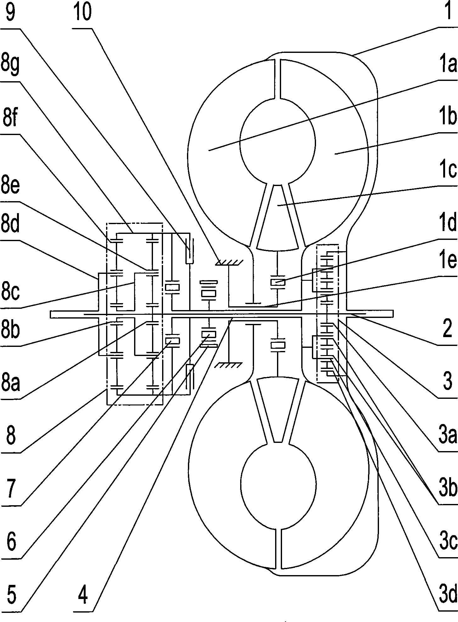
[0007] Specific implementation mode one: combine figure 1 Describe this embodiment, the self-coupling continuously variable transmission of this embodiment consists of a torque converter 1, an intermediate shaft 2, a differential planetary row 3, a long hollow shaft 4, a brake 5, a second one-way clutch 6, and a third one-way clutch 7. Composed of a variable speed planetary row 8 and a two-way clutch 9; the torque converter 1 is composed of a pump wheel 1a, a turbine 1b, a guide wheel 1c, a first one-way clutch 1d and a short hollow shaft 1e, and the differential planetary row 3 It is composed of differential sun gear 3a, differential planetary gear 3b, differential planetary carrier 3c and differential ring gear 3d. The differential planetary row 3 is set in the torque converter 1, and the torque converter 1 is set on the intermediate shaft 2, the variable speed planetary row 8 is composed of the front sun gear 8a, the rear sun gear 8b, the front planet carrier 8c, the rear p...
specific Embodiment approach 2
[0008] Specific implementation mode two: combination figure 1 Describe this embodiment, between the intermediate shaft 2 and the long hollow shaft 4 of this embodiment, between the long hollow shaft 4 and the short hollow shaft 1e, between the front planetary carrier 8c and the intermediate shaft 2, between the rear planetary carrier 8d and the Both the intermediate shafts 2 and the torque converter 1 and the intermediate shaft 2 are rotationally fitted. Such setting can ensure the smooth and reliable rotation of the transmission. Others are the same as in the first embodiment.
[0009] The working principle is: the self-coupled continuously variable transmission of the present invention is based on coaxial gear transmission, supplemented by hydraulic transmission, and the power is divided into two ways and transmitted to the rear planetary carrier 8d for synthesis and output. The gear transmission route is differential The inner ring gear 3d is at the same speed as the engi...
PUM
 Abstract
Description
Claims
Application Information