Method and apparatus for measuring and compensating transmission error of electric cylinder

A transmission error and electric cylinder technology is applied in the field of detecting and compensating devices, measuring and compensating electric cylinder transmission errors. The effect of improving control accuracy

Inactive Publication Date: 2009-07-22
PLA AIR FORCE AVIATION UNIVERSITY
View PDF0 Cites 26 Cited by
  • Summary
  • Abstract
  • Description
  • Claims
  • Application Information

AI Technical Summary

Problems solved by technology

The disadvantage of this method of measuring the transmission error of the electric cylinder is that it does not consider the influence of the transmission error under the reversing and variable loads when the electric cylinder is moving.
Therefore, when the control computer performs transmission error compensation, over-compensation or under-compensation is prone to occur.

Method used


Image

  • Method and apparatus for measuring and compensating transmission error of electric cylinder

Examples


Embodiment 1

[0023] (1) Transmission error measurement

[0024] Transmission error is divided into two parts, pitch error and backlash error. When measuring the pitch error, we apply different loads to the electric cylinder. Since the influence of variable load is considered when measuring the pitch error, the backlash error is no longer loaded.

[0025] In order to obtain the pitch error data of the electric cylinder with variable load, we measure the pitch error in two cases, no-load and full-load, to lay the foundation for interpolation calculation. The method and steps of the two error measurements are the same. First, the electric cylinder rod is divided into several compensation intervals on average, and the control computer controls the electric cylinder to execute the zero return command. The zero position of the electric cylinder rod is the coordinate zero point; The compensation amount is set to zero value, and this position is used as the measurement reference. After the comma...

Embodiment 2

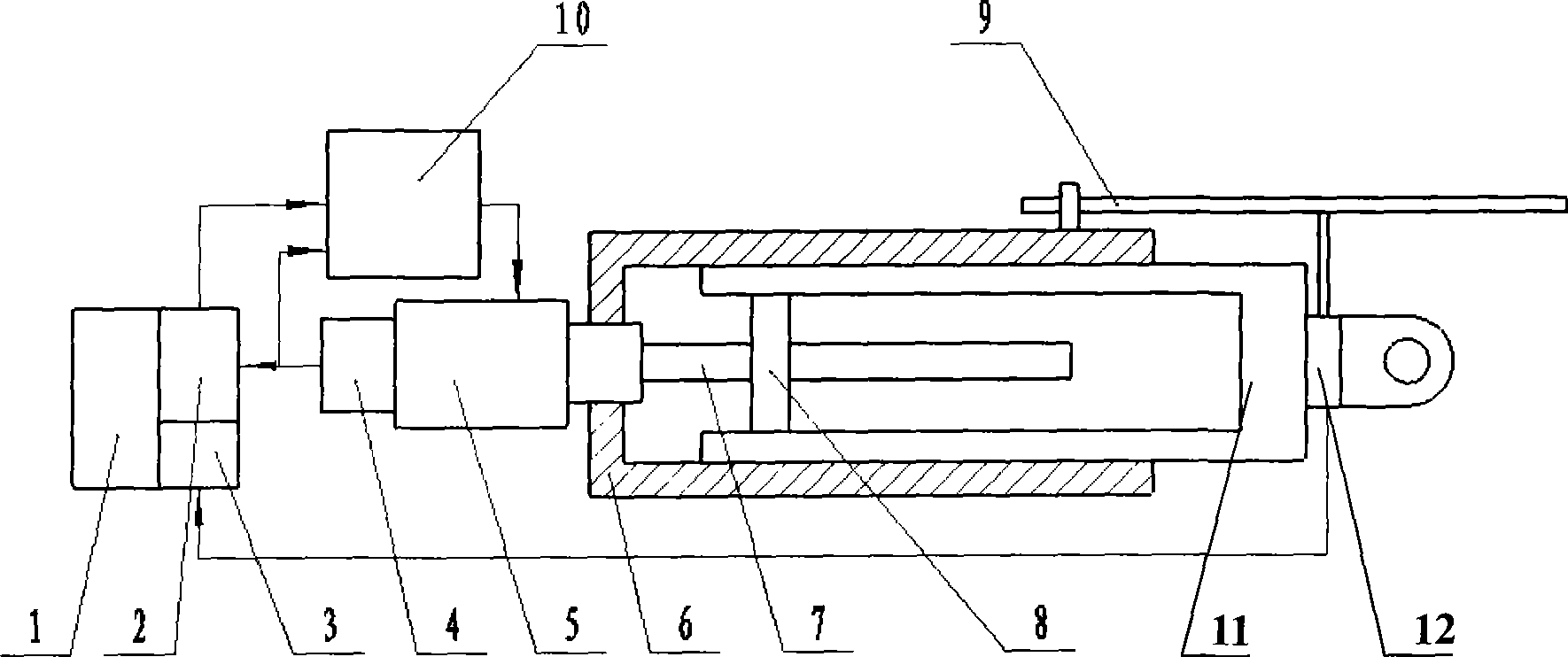
[0030] according to figure 1 , the electric cylinder control and measurement system of the present invention consists of a control computer 1, a position controller 2, a servo driver 10, an encoder 4, an AC servo motor 5, an electric cylinder housing 6, a lead screw 7, a nut 8, and an electric cylinder output rod 11 , strain gauge force sensor 12, digital display magnetic ruler 9 and A / D interface card 3 constitute. The control computer 1 is used to send the motion control command of the servo motor 5, the transmission error compensation command, and collect the force sensor signal; the position controller 2 is connected to the bus of the computer 11, and the position controller 2 drives the servo motor to rotate through the servo driver 10, and the feedback The encoder 4 is installed on the shaft of the servo motor, the servo motor 5 rotates through the coupling with the lead screw 7 and the nut 8, and the nut 8 moves linearly with the electric cylinder output rod 11; the str...


PUM


Abstract

The invention is a method and a device for measuring and compensating transmission error of electric cylinders; a control computer transmits position commands to a position controller for signal conversion via software, and a servo driver drives an alternating current servo motor to rotate so as to drive an ejector rod of the electric cylinder to have a straight line motion; an encoder outputs feedback signals to the position controller, and the position commands are compared with the feedback signals output by the encoder; when the ejector rod of the electric cylinder has a straight line motion, a digital display magnetoscale measures the travel route; a strain gauge force sensor is used for detecting the load supported by the ejector rod of the electric cylinder, and the load value is converted into analog voltage signals that are input to an A/C interface card; the A/C interface card converts the analog voltage signals to digital signals which are input to the control computer. To give full consideration to influence factors of transmission error in inverting and oscillating load when the electric cylinder moves, when the control computer compensates transmission error, over compensation or undercompensation of the electric cylinder is avoided, thereby improving the control precision of electric cylinders.

Description

technical field [0001] The invention is a method for measuring and compensating the transmission error of an electric cylinder, and also provides a detection and compensation device suitable for the method, belonging to the field of automatic control and mechanical detection devices Background technique [0002] The electric cylinder is the key moving part of the six-degree-of-freedom electric motion platform. Usually, the transmission error of the electric cylinder is measured by using a standard displacement sensor to measure the length of the electric cylinder. The difference between the measured length and the command length value given by the control computer is the transmission error of the electric cylinder. The disadvantage of this method of measuring the transmission error of the electric cylinder is that it does not consider the influence of the transmission error under the commutation and variable load when the electric cylinder moves. Therefore, when the contro...

Claims


Application Information

Patent Timeline
Patent Type & Authority Applications(China)
IPC IPC(8): G01B7/02G05D3/12G05D3/20
Inventor 梁建民王勇亮赵成仁
Owner PLA AIR FORCE AVIATION UNIVERSITY
Why Eureka
Try Eureka