
Strain gauge and its production method

A technology of strain gauges and polymers, applied in the field of strain gauges, can solve problems such as inability to measure large displacements

Active Publication Date: 2009-07-22
THE HONG KONG POLYTECHNIC UNIV
View PDF0 Cites 1 Cited by
  • Summary
  • Abstract
  • Description
  • Claims
  • Application Information

AI Technical Summary

Problems solved by technology

[0003] The technical problem to be solved by the present invention is to provide a strain gauge capable of measuring large displacement and its manufacturing method in view of the defect that the prior art cannot measure large displacement

Method used


Image

  • Strain gauge and its production method
  • Strain gauge and its production method
  • Strain gauge and its production method

Examples


Embodiment Construction

[0025] The following descriptions of certain exemplary embodiments of the invention are exemplary in nature only and are not intended to limit the invention and its application or uses.

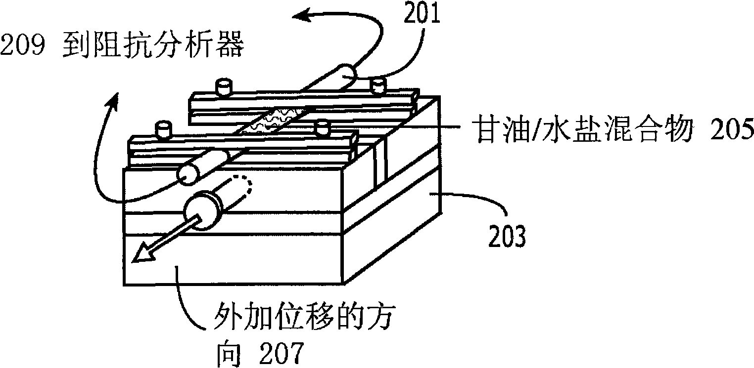
[0026] Please refer to the following Figure 1 to Figure 4 .

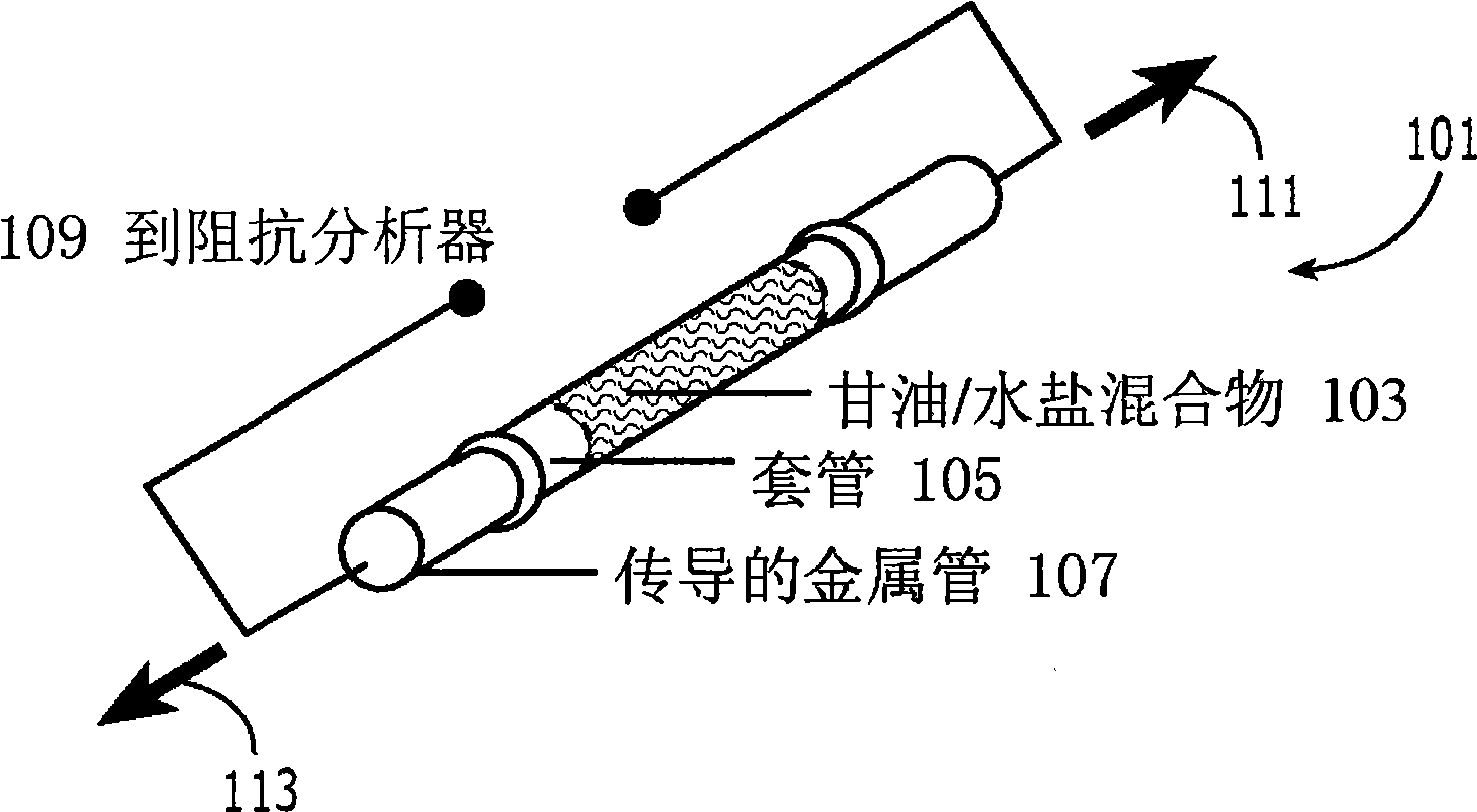
[0027] figure 1 is an embodiment of a strain gauge 101 of the present invention comprising a glycerin / water salt mixture 103 as the internal fluid of a polymeric sleeve 105 to which metal tubes 107 are connected at both ends. A lead block 107 is attached to the end of a metal tube 107 for feedback to an impedance analyzer that changes the current measurement.

[0028] The strain gauge length (the length between the two electrodes) of the bushing 105 used in the strain gauge 105 ranges from 15mm to 30mm. The sleeve 105 may be circular or other suitable shape with a radius of about 1 mm to 5 mm. The sleeve 105 may be made of a polymer, such as an elastic or rubber-like polymer. Both ends of the sleeve 105 are sealed to accommod...


PUM


Abstract

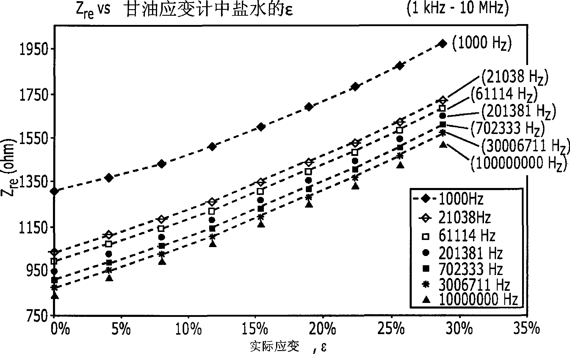
The present invention relates to a strain gauge having a conductive fluid made of a glycerin / aqueous salt mixture, and methods of making the strain gauge. The strain gauge comprises a polymer sleeve; a fluid piezoresistive material made by the glycerin / aqueous salt mixture; a metal tube, a metal conductive pad or a conductive polymer pad arranged on both ends of the polymer sleeve, wherein the fluid piezoresistive material is included in the polymer sleeve. According to the invention, the strain gauge is capable of measuring large displacement of around 30% true strain.

Description

technical field [0001] The present invention relates to a strain gauge, and more particularly, to a fluid piezoresistive strain gauge and a manufacturing method thereof. Background technique [0002] A strain gauge is a device used to measure spatial changes in a specimen. Electronic strain gauges, which are based on the measurement of a change in electrical resistance proportional to strain, are widely used today. The principle of resistance strain gauge can be explained by rod conduction. The rod is elongated in response to tensile stress, increasing in length while the resistivity of its material remains constant. The displacement is translated by movement to a rotatable pointer opposite the dial of the calibrated pressure valve. Strain gauges that display in digital form typically include electronic pressure sensors, such as piezoelectric-type sensors, that generate an electrical signal in response to the pressure revealed by the sensor. The electrical signal is then...

Claims


Application Information

Patent Timeline
Patent Type & Authority Applications(China)
IPC IPC(8): G01B7/16
CPCG01B7/18
Inventor 郑庆祥钞晨张燕妮
Owner THE HONG KONG POLYTECHNIC UNIV
Learn More