Homeotropic liquid crystal display panel

A liquid crystal display panel, vertical alignment technology, applied in instruments, nonlinear optics, optics, etc., can solve the problems of light leakage, inability to effectively block light leakage, and affect the display contrast and display quality of the liquid crystal display panel 100, and achieve the effect of wide viewing angle

Active Publication Date: 2009-07-22
AU OPTRONICS CORP
View PDF0 Cites 5 Cited by
  • Summary
  • Abstract
  • Description
  • Claims
  • Application Information

AI Technical Summary

Problems solved by technology

[0006] However, when the vertically aligned liquid crystal display panel 100 displays images, the liquid crystal molecules 132 around the alignment protrusions 104 cannot be tilted regularly due to the topographical changes caused by the alignment protrusions 104, resulting in light leakage.
Moreover, since the angle between the alignment protrusion 104 and the light transmission axes 142a, 142b is 45 degrees, the long axis direction 134 of the liquid crystal molecules 132 around the protrusion 104 and the light transmission axes 142a, 142b are formed in an angle of 45 degrees. In this way, the polarizer 140a and the polarizer 140b will not be able to effectively block the light leakage generated around the alignment protrusion 104, so that part of the light leakage is emitted out of the vertical alignment liquid crystal display panel 100.
The above-mentioned light leakage problem is especially serious when the liquid crystal display panel 100 displays dark images, which will affect the display contrast and display quality of the liquid crystal display panel 100

Method used


Image

  • Homeotropic liquid crystal display panel
  • Homeotropic liquid crystal display panel
  • Homeotropic liquid crystal display panel

Examples


Embodiment Construction

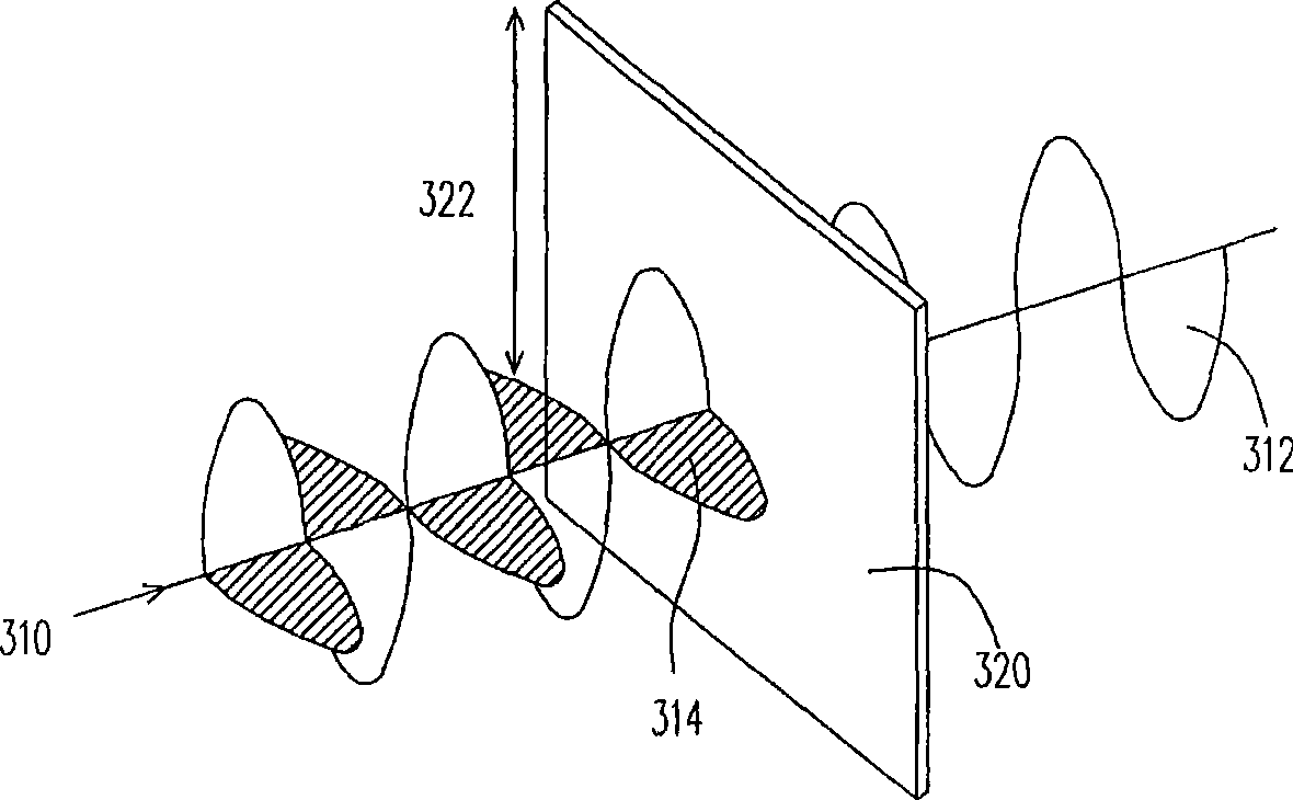
[0077] image 3 A schematic diagram of light passing through a single polarizer is shown. Figure 4 A schematic diagram showing light passing through a pair of crossed polarizers sandwiching a liquid crystal layer. Please refer to image 3 , generally speaking, when the light 310 is incident on a single polarizer 320, it can be polarized and divided into two perpendicular directions, wherein the light 312 parallel to the light transmission axis 322 of the polarizer 320 can pass through, while the light ray 312 perpendicular to the light transmission axis 320 can pass through. Light ray 314 on axis 322 is absorbed.

[0078] Then please refer to Figure 4 When the light 410 passes through the polarizer 420, the liquid crystal layer 430 and the polarizer 440, the liquid crystal molecules 432 in the liquid crystal layer 430 between the polarizers 420, 440 will cause phase retardation (phase retardation) in the polarization direction of the light 410 , wherein the light paralle...


PUM


Abstract

A homeotropic alignment liquid crystal display panel with pixel region comprises a first substrate, a second substrate, a plurality of strip-shaped alignment bulges, a liquid crystal layer configured between the two substrates as well as a first polarizer and a second polarizer respectively arranged at the other side of the first substrate and the second substrate. At least part of the strip-shaped alignment bulges are positioned on the first substrate. A plurality of liquid crystal molecules are arranged in the liquid crystal layer and show diverse tilting directions by the corresponding strip-shaped alignment bulges. A first light penetrating axis of the first polarizer and a second light penetrating axis of the second polarizer are orthogonal. The strip-shaped alignment bulges are consistently folded strip-shaped bulges composed by a plurality of first alignment sections and a plurality of second alignment sections by alternatively connecting, the extending directions of the first alignment sections and the second alignment sections are in parallel with the first light penetrating axis and the second light penetrating axis. The invention can achieve the multi-range alignment wide viewing angle effect, can block light leakage and can increase the contrast ratio of the display image and show excellent effect.

Description

technical field [0001] The present invention relates to a liquid crystal display panel, in particular to a vertical alignment liquid crystal display (VA-LCD) capable of improving light leakage and improving image contrast. Background technique [0002] Existing liquid crystal display panels tend to develop towards high brightness, high contrast, large-area display and wide viewing angle. In order to overcome the viewing angle problem of large-sized liquid crystal display panels, the wide viewing angle technology of liquid crystal display panels must also be constantly improved and developed. breakthrough. Among them, Vertical Alignment Liquid Crystal Display (VA-LCD) is currently a relatively common liquid crystal display panel used in wide viewing angle technology. [0003] For a general vertically aligned liquid crystal display panel, the protrusions or slits arranged on the color filter substrate or the active element array substrate can make the liquid crystal molecules...

Claims


Application Information

Patent Timeline
Patent Type & Authority Applications(China)
IPC IPC(8): G02F1/1337G02F1/1343G02F1/1335G02F1/139
Inventor 李锡烈吕英齐
Owner AU OPTRONICS CORP
Why Eureka
Try Eureka