
Centrifugal separator

A centrifugal separator and liquid technology, applied in separation methods, dispersed particle separation, chemical instruments and methods, etc., can solve the problems that the efficiency and dehumidification effect need to be improved

Inactive Publication Date: 2009-07-29
FRAMATOME ANP
View PDF0 Cites 26 Cited by
  • Summary
  • Abstract
  • Description
  • Claims
  • Application Information

AI Technical Summary

Problems solved by technology

In addition, the efficiency of liquid separation compared to the energy input and the absolute dehumidification effect need to be improved

Method used


Image

  • Centrifugal separator
  • Centrifugal separator

Examples


Embodiment Construction

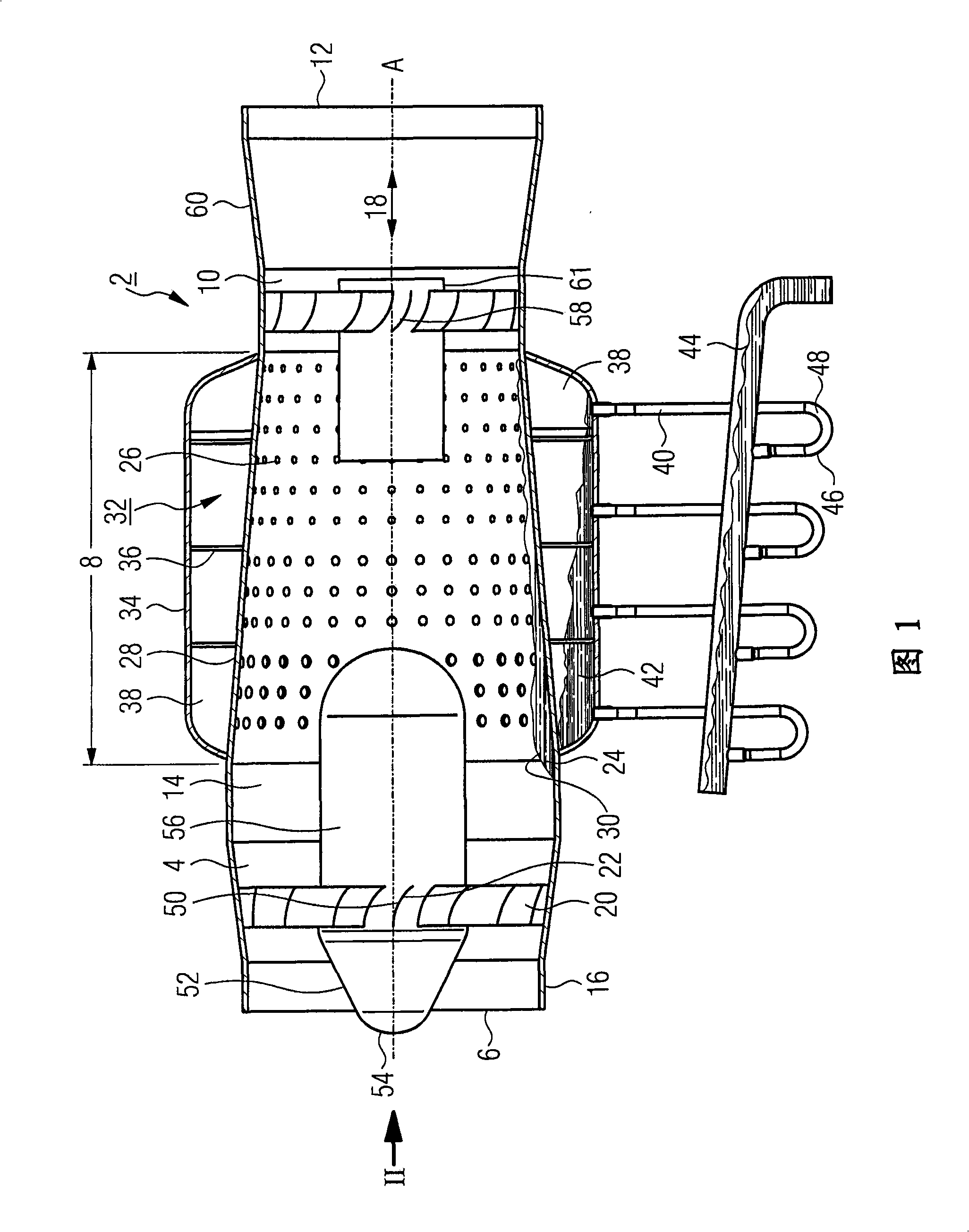
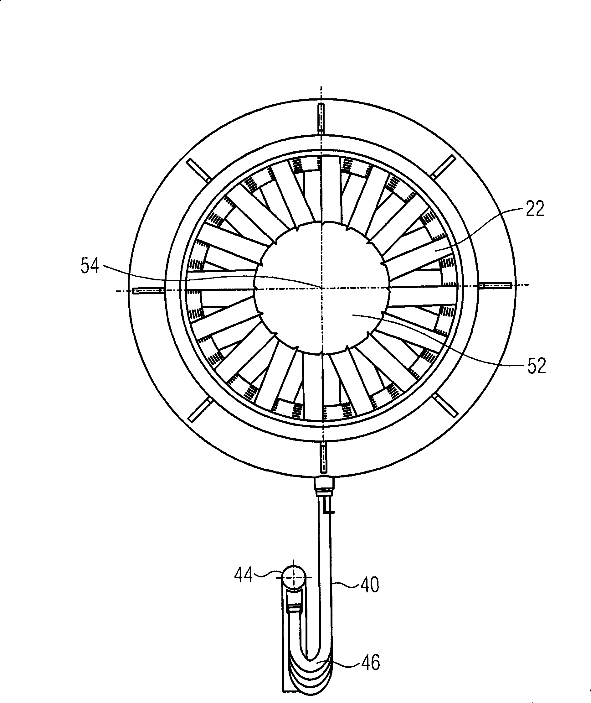
[0019] In Figure 1 and figure 2 The centrifugal separator 2 shown in is used to remove water droplets from the water-steam cycle of a power station, in particular from the high-pressure turbine to the reheater line (not shown here) before the low-pressure turbine ) pre-separated or coarsely separated from the wet vapor stream in the overflow tube. A water separator can be connected here between the centrifugal separator 2 and the reheater tube, the latter being unloaded by the centrifugal separator 2 .

[0020] The centrifugal separator 2 comprises an inlet area 4 with inlet openings 6 for the gas or vapor flow to be dehumidified, a separation section 8 in which the liquid is separated, and an outlet area 10 with outlet openings 12 . Between the inlet opening 6 and the outlet opening 12 a gas or vapor flow is guided in a flow channel 14 which is delimited to the outside by an inner housing 16 with a suitably defined contour.

[0021] The flow channel 14 is aligned along an a...


PUM


Abstract

The invention relates to a centrifugal separator (2) for separating liquid from airflow carrying liquid or steam, which is provided with a flow path (14) limited by a secured inner shell (16) and aligned along an axial direction (18), where the separator (8) should be provided with particularly silent working property with less vibration under a condition of high separating efficiency. Therefore, according to this invention, the centrifugal separator (2) is provided with plural liquid collecting chambers (38) arranged one by one in the axial direction (18) in an area of a separated section (8) and disposed respectively around the inner shell (16) circularly, and sealed by a divided plate (36) to each other respectively, wherein each liquid collecting chamber (38) is connected with the flow path (14) through plural through holes (26) led into the inner shell (16) by flow technology.

Description

technical field [0001] The present invention relates to a centrifugal separator for separating liquid from a liquid or vapor laden gas stream having flow channels aligned in the axial direction bounded by a fixed inner casing. Background technique [0002] Centrifugal separators, also known as cyclones, are also used for separating solid or liquid particles contained in gases, especially for separating water droplets from water-vapor mixtures. For this purpose, the liquid- or moist-vapour-laden gas flow is converted into a swirling motion inside the flow channel. Due to the effect of centrifugal force and the greater inertia of liquid particles compared to gas particles, liquid particles accumulate in the outer edge region of the flow channel on the walls delimiting the flow channel, where they are collected and discharged while being dehumidified in this way The gas flow itself leaves the flow channel through the central region of the flow channel. [0003] In centrifugal...

Claims


Application Information

Patent Timeline
IPC IPC(8): B04C3/00
CPCB01D45/16B04C3/06B04C3/00
Inventor 尼古拉·科列夫马克斯·黑勒斯特凡·韦德金德
Owner FRAMATOME ANP
Learn More