Needle bar swinging mechanism of sewing machine

A swing mechanism and sewing machine technology, applied in the direction of sewing machine needle holders, sewing machine components, sewing equipment, etc., can solve the problems of cost increase, cost increase, and complex motor composition, and achieve reduced capacity, miniaturization, high speed and high speed. The effect of precision zigzag sewing

Inactive Publication Date: 2012-09-05
AISIN SEIKI KK
View PDF2 Cites 0 Cited by
  • Summary
  • Abstract
  • Description
  • Claims
  • Application Information

AI Technical Summary

Problems solved by technology

[0006] However, since the ball screw or roller screw used in Patent Document 1 is a part that requires precision machining and assembly, it leads to an increase in cost
In addition, since two stepping motors are used as actuators in Patent Document 2, a space for arranging the two motors is required.
Also, the composition for coordinating the driving of the two motors is also more complicated, so it will also increase the cost

Method used


Image

  • Needle bar swinging mechanism of sewing machine
  • Needle bar swinging mechanism of sewing machine
  • Needle bar swinging mechanism of sewing machine

Examples


Embodiment approach 1

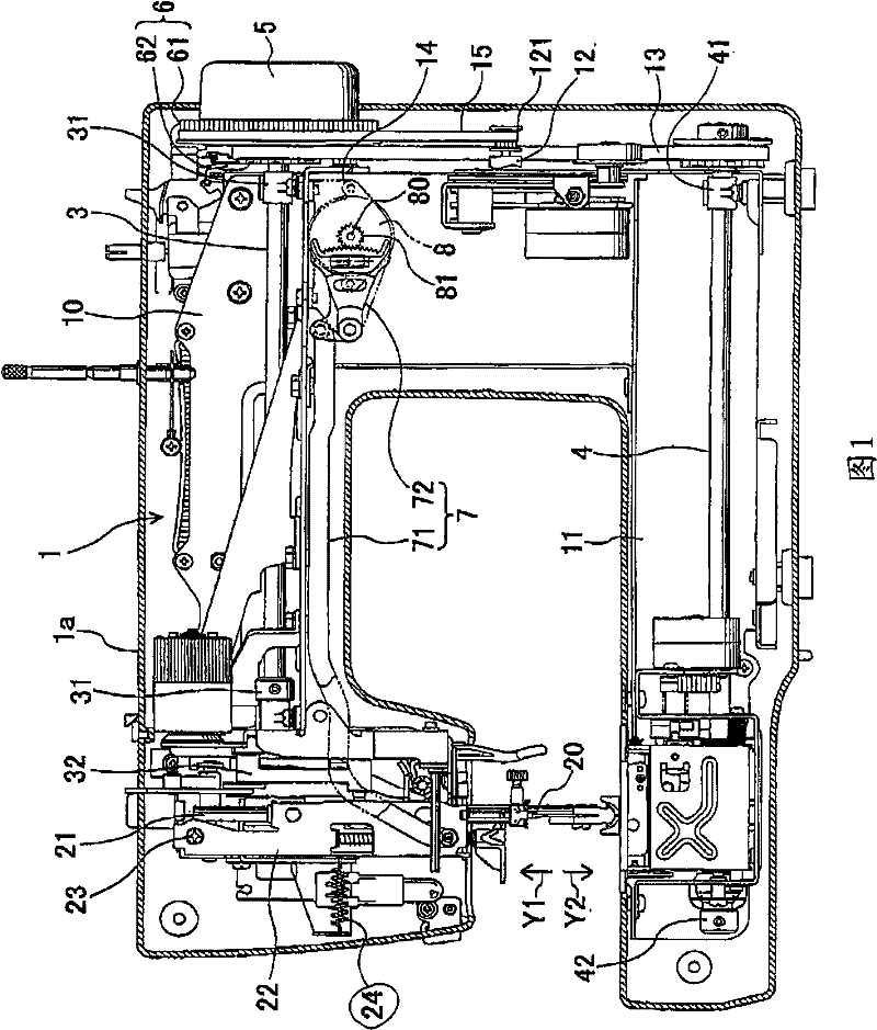
[0028] Such as figure 1 As shown, a body 1 as a main component of the sewing machine is covered by a casing 1 and includes a cantilever frame 10 and a base frame 11 . The cantilever frame 10 and the base frame 11 are not castings, but mainly formed of a sheet metal formed body formed by stamping a metal plate having a predetermined thickness. On the cantilever machine frame 10, a needle bar 21 capable of holding a needle 20 is provided so as to be movable up and down, and an upper shaft 3 along the horizontal direction is provided rotatably. The upper shaft 3 is supported and freely rotatable by a pair of bearings 31 fixed to the boom frame 10 . One end of upper shaft 3 fixes hand wheel 5 and pulley 6 ( figure 1 center right). The pulley 6 is formed with a driven wheel 61 of a large diameter portion and a first timing wheel 62 . Below the pulley 6, the drive belt 15 is suspended between the motor pulley 121 fixed on the drive motor 12 fixed to the cantilever machine frame ...

Embodiment approach 2

[0039] The sewing machine in the second embodiment has almost the same configuration as the sewing machine in the first embodiment, except for the needle bar holding arm 22 and the needle bar spring 24, and has the same effects as those in the first embodiment. Therefore, a detailed description of the same configuration as that of Embodiment 1 is omitted.

[0040] Such as Figure 4 As shown, in the sewing machine according to the second embodiment, the needle bar holding arm 22 is urged in one direction in the left-right direction by the needle bar urging member (urging member) 25 . The needle bar holding arm 22 has an engaging portion 221 formed on a side surface (left side in the figure). Furthermore, the needle bar urging member 25 has a pressing member 251 and a torsion spring 252 . The pressing member 251 has a contact portion 253 that contacts the engaging portion 221 of the needle bar holding arm 22 and pushes the needle bar holding arm 22 in one direction, and a lock...


PUM


Abstract

This invention provides a needle bar swinging mechanism that has simple structure, and can restrain the cost increment and realize the shake-free zigzag sewing with high speed and high precision. The needle bar swinging mechanism of this invention comprises a needle bar (21); a needle bar holding arm (22) that can vertically move to hole the needle bar (21); a connecting rod (7) whose one end is held at the needle bar holding arm (22); a motor (8) that is connected with the other end of the connecting rod (7) and makes the needle bar (21) swing in the left and right directions; a force applying component (24) that applies force to the needle bar holding arm (22) and the connecting rod (7) facing to one direction of the left and right directions of the needle bar (21) swinging; an auxiliary force applying component (9) that applies force to the needle bar holding arm (22) and the connecting rod (7) facing to the other direction for conquering the acting force of the force applying component (24).

Description

technical field [0001] The invention relates to a needle bar swinging mechanism of a sewing machine with zigzag sewing (zigzag sewing) function. Background technique [0002] One of the functions of the sewing machine has so-called zigzag sewing (zigzag sewing), which is to sew by swinging the needle bar left and right relative to the direction in which the cloth is sewn. Conventionally, an actuator is used to swing a rod-shaped link, and by mechanically transmitting the swing, the needle bar swings left and right to sew a zigzag pattern. In the proposal disclosed in Patent Document 1, a stepping motor is used as an actuator, and the reciprocating rotational motion of the driven shaft (rotary shaft) of the stepping motor is converted into reciprocating linear motion by a transmission mechanism using a screw. And, this reciprocating linear motion is converted into an oscillating motion by a link to oscillate the needle bar. In addition, Patent Document 2 discloses an invent...

Claims


Application Information

Patent Timeline
Patent Type & Authority Patents(China)
IPC IPC(8): D05B55/14D05B3/02
Inventor 福田达则
Owner AISIN SEIKI KK
Why Eureka
Try Eureka