Cable locating jig and cable wire stripping method based on the same

A technology for positioning fixtures and cables, which is applied in the directions of equipment, circuits, and electrical components for dismantling/armoring cables. It can solve problems such as low efficiency and difficulty, and achieve the effect of easy fixing.

Inactive Publication Date: 2009-07-29
张志辉
View PDF0 Cites 8 Cited by
  • Summary
  • Abstract
  • Description
  • Claims
  • Application Information

AI Technical Summary

Problems solved by technology

[0003] In the prior art, special wire stripping equipment can be used to realize three-layer wire stripping at the same time, but the efficiency is not high, and manual inspection is required. The price of this equipment is not low, and operat

Method used


Image

  • Cable locating jig and cable wire stripping method based on the same
  • Cable locating jig and cable wire stripping method based on the same
  • Cable locating jig and cable wire stripping method based on the same

Examples


Example Embodiment

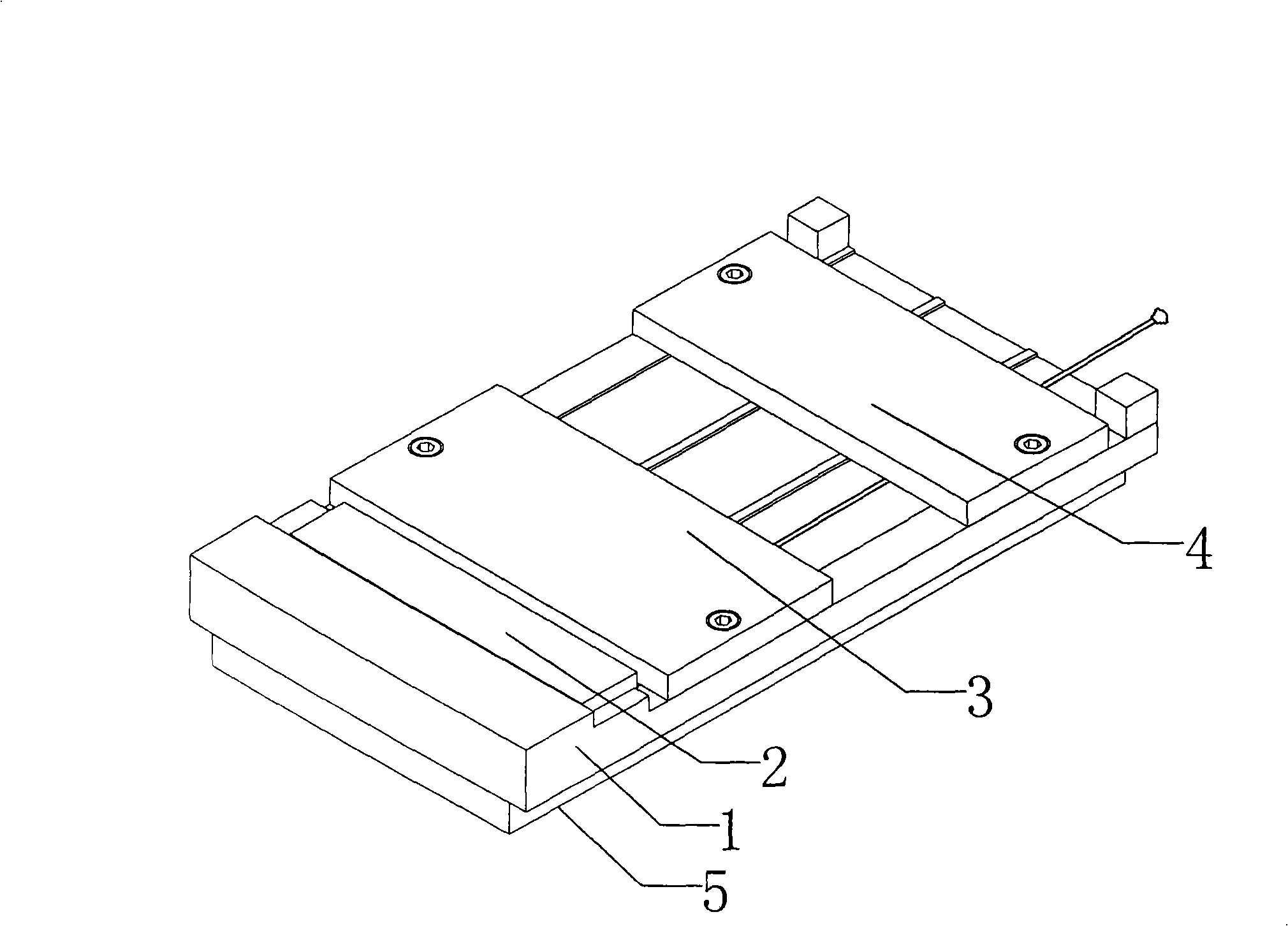
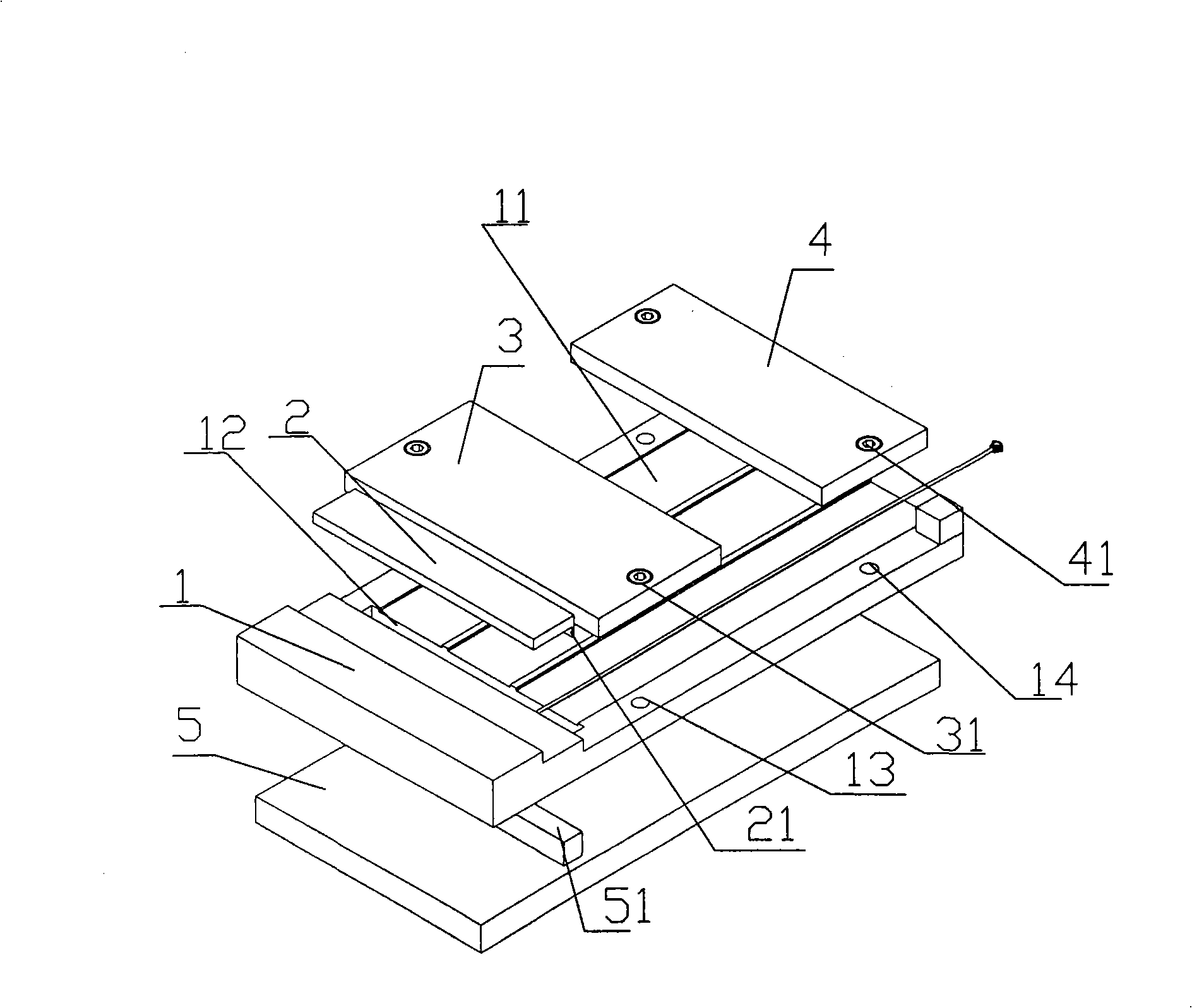
[0024] to combine figure 1 and figure 2 , the following further describes the cable positioning fixture:

[0025] A cable positioning jig, comprising a base plate 1, a buckle plate 2, a front cover plate 3 and a rear cover plate 4, the base plate is provided with a table 11 on which cable groups can be placed side by side, and the front end of the table is provided with a hole for laser to penetrate the cable group Laser groove 12, the laser groove and the cable group are vertically arranged; the pinch plate 2 is located on the substrate on one side of the laser groove 12, and has a vertical surface 21 that facilitates the alignment of the ends of the cable group; the front cover 3 is located on the laser On the table 11 on the other side of the groove 12, at least a pair of positioning rods 31 and a positioning hole 13 for pressing the head of the cable set are respectively provided between the front cover 3 and the base plate 1 . The front cover can be integrally formed w...


PUM


Abstract

The invention discloses a cable locating jig, which comprises a substrate, a buckle plate, and a front cover plate; the substrate is provided with a table facet for placing a cable group; a laser groove is arranged at the front end of the table facet; the buckle plate is arranged on one side of the laser groove and is provided with an upright plane convenient for aligning with an end head of the cable group; the front cover plate is arranged on the other side of the laser groove; a pair of locating rods and a pair of locating holes are respectively arranged between the front cover plate and the substrate, which are convenient for compressing the head of the cable group; the abreast cable groups are arranged on the table facet of the substrate; the end head of the cable group is aligned with the upright plane of the buckle plate; and then the front cover plate and a back cover plate are respectively fixed on the table facet through covering the locating rods and the locating holes; the cable locating jig is arranged on a laser engraving machine; after the locating table facet is put on the laser groove, exterior coating of the cable is burnt; the cable group with coating pulled out is then dipped in tin at a position of an exposed cable mesh grid and is placed on the cable locating jig again; the mesh grid is burnt by the laser engraving machine; the cable group with the mesh grid removed is placed on the cable locating jig again; and an insulating layer is burnt by the laser engraving machine.

Description

technical field [0001] The invention relates to a cable fixing device and a wire stripping method, in particular to a jig for fixing and placing cables and a cable stripping method based on the jig. Background technique [0002] Microelectronic products such as mobile phones and notebook computers are inseparable from ultra-thin coaxial cables. At present, the diameter of the cables is very small, ranging from 2mm to 1mm, and even below 1mm. It includes multiple layers, usually three layers: The outermost layer is called the covering skin, the second layer is a conductive braided mesh, the third layer is an insulating layer (Teflon hose), and the innermost layer is a central wire, which usually consists of 5-7 wires with a diameter of 0.08mm-0.07 mm ultra-fine wire composition. In practical application, the cable must be peeled off the sheath, braided mesh and insulation layer in turn, and then use a special riveting tool with a special riveting terminal to make a cable con...

Claims


Application Information

Patent Timeline
IPC IPC(8): H01R43/28H02G1/12
Inventor 张志辉
Owner 张志辉
Why Eureka
Try Eureka