Output control method for welding power supply
A technology of welding power supply and output control, applied in welding equipment, manufacturing tools, arc welding equipment, etc., to achieve the effect of improving welding quality and stability
- Summary
- Abstract
- Description
- Claims
- Application Information
AI Technical Summary
Problems solved by technology
Method used
Image

Examples
Embodiment approach 1
[0080] The basic calculation formula used for the output control method of the welding power source concerning this invention is demonstrated below. Between the output voltage setting value Er, the inductance setting value Lr, the external characteristic slope setting value Rr, the welding current i, the welding voltage v, and the welding current control setting value Irc, the above formula (2) is established.
[0081] Irc=∫((Er—v—Rr·i) / Lr)·dt
[0082] Here, (Er−Rr·i) represents the external characteristic as described above, so when it is extended and replaced with the function Er(i), it becomes the following formula.
[0083] Irc=∫((Er(i)—v) / Lr)·dt...(3) formula
[0084] This calculation formula is a basic calculation formula of the present invention.
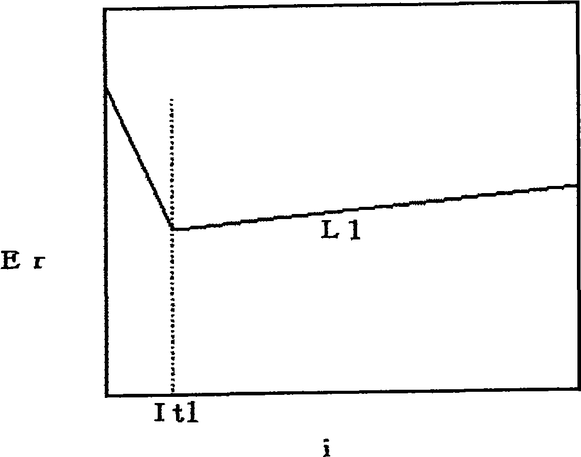
[0085] figure 1 It is a graph showing an example of the function Er(i) of the external characteristic shown by the broken line. In this figure, the horizontal axis represents the welding current i, and the vertical axis ...
Embodiment approach 2
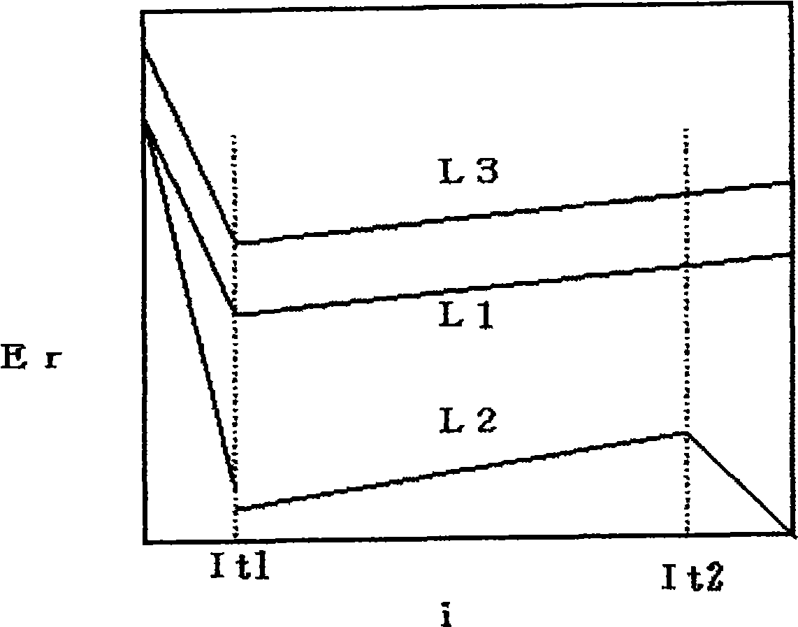
[0102] image 3 It is a graph showing the external characteristic function related to Embodiment 2 of the present invention. In this figure, the horizontal axis represents the welding current i, and the vertical axis represents the output voltage setting value Er. This figure is similar to the above figure 1 Correspondingly, the external characteristics L1 are the same. Hereinafter, description will be made with reference to this figure.
[0103] This graph is composed of three external characteristics L1-L3. The function of the external characteristic L1 is the above (4)
[0104] and (5) formula. The external characteristic L2 is the following function.
[0105] i≦It1 Er=a21·i+b21
[0106] It1
[0107] It2
[0108] In addition, the external characteristic L3 can be expressed by the following formula.
[0109] i≦It1 Er=a31·i+b31
[0110] It1
[0111] The welding state of the external characteristic L1 is an arc gene...
PUM
 Abstract
Description
Claims
Application Information
 - Generate Ideas
- Intellectual Property
- Life Sciences
- Materials
- Tech Scout
- Unparalleled Data Quality
- Higher Quality Content
- 60% Fewer Hallucinations
Browse by: Latest US Patents, China's latest patents, Technical Efficacy Thesaurus, Application Domain, Technology Topic, Popular Technical Reports.
© 2025 PatSnap. All rights reserved.Legal|Privacy policy|Modern Slavery Act Transparency Statement|Sitemap|About US| Contact US: help@patsnap.com