Uniform illuminating device

A technology of uniform light emission and light-emitting surface, applied in the direction of lighting devices, lighting device parts, light sources, etc., can solve the problems such as vignetting of the light-emitting cover, affecting the heat dissipation of light-emitting diodes, affecting the system effect, etc., to achieve high utilization of light energy, Avoid halo or flare phenomenon, uniform light receiving effect

Inactive Publication Date: 2009-08-05
EDEE MARKETING
View PDF1 Cites 9 Cited by
  • Summary
  • Abstract
  • Description
  • Claims
  • Application Information

AI Technical Summary

Problems solved by technology

[0005] The disadvantage of the above-mentioned signboard light box system is that only one light-emitting diode is installed in the reflector, and its power is relatively large. For irregular-shaped light-emitting covers, due to the fixed irradiation direction of the light-emitting diodes, dark corners will appear on the side walls of the light-emitting cover, and the light Unable to uniformly illuminate all corners of the side wall of the light cover
And this opaque layer blocks part of the light emitted by the light-emitting diode, reduces the luminous efficiency of the light-emitting diode, causes the luminous flux to reduce, and wastes energy; as

Method used


Image

  • Uniform illuminating device
  • Uniform illuminating device
  • Uniform illuminating device

Examples


example

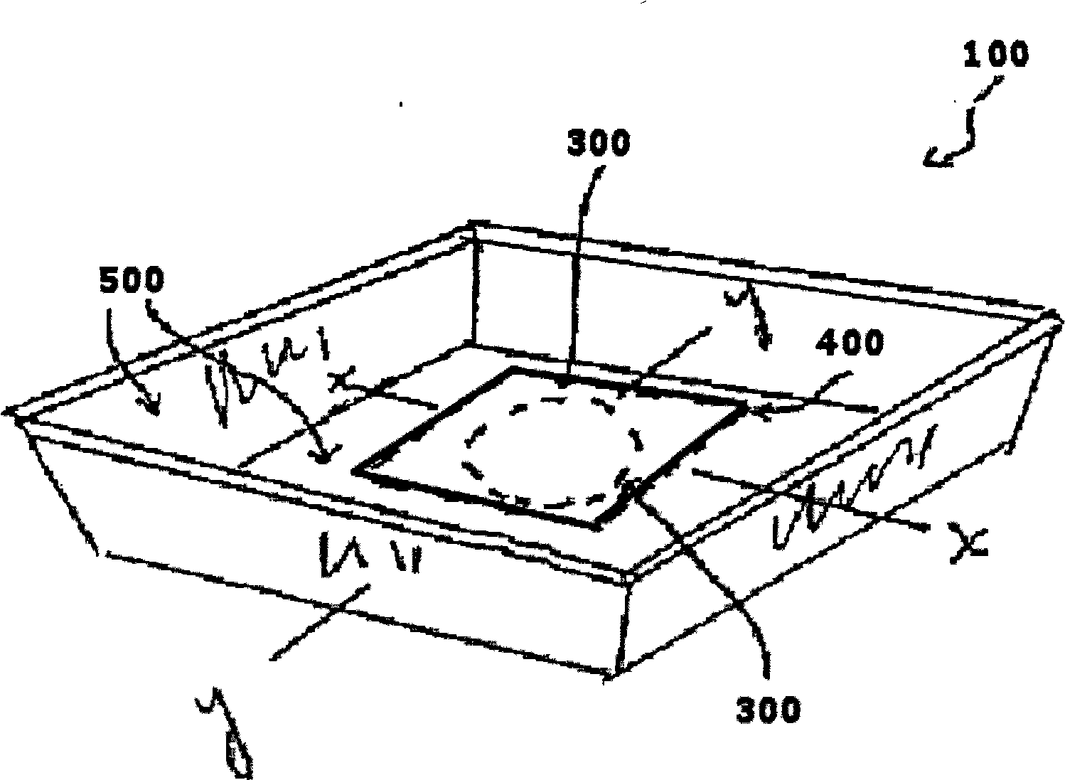
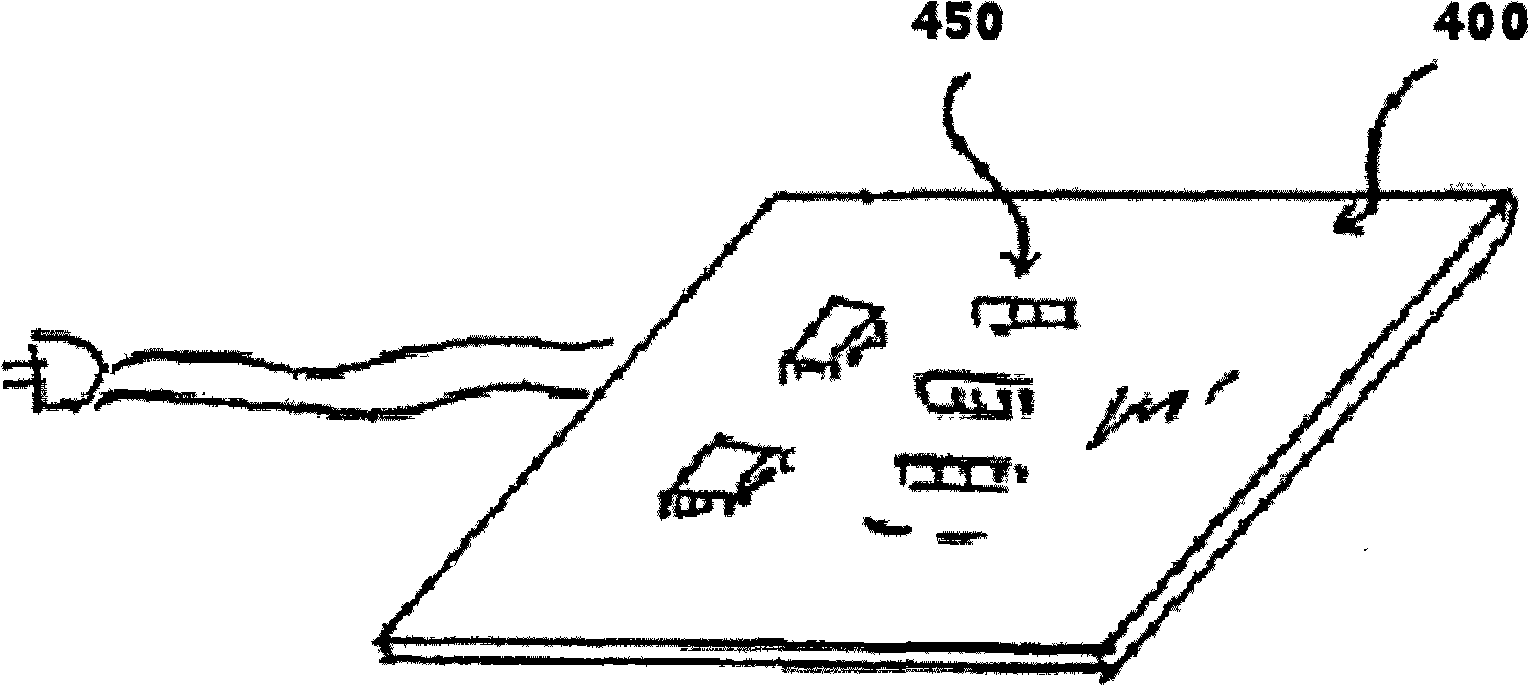
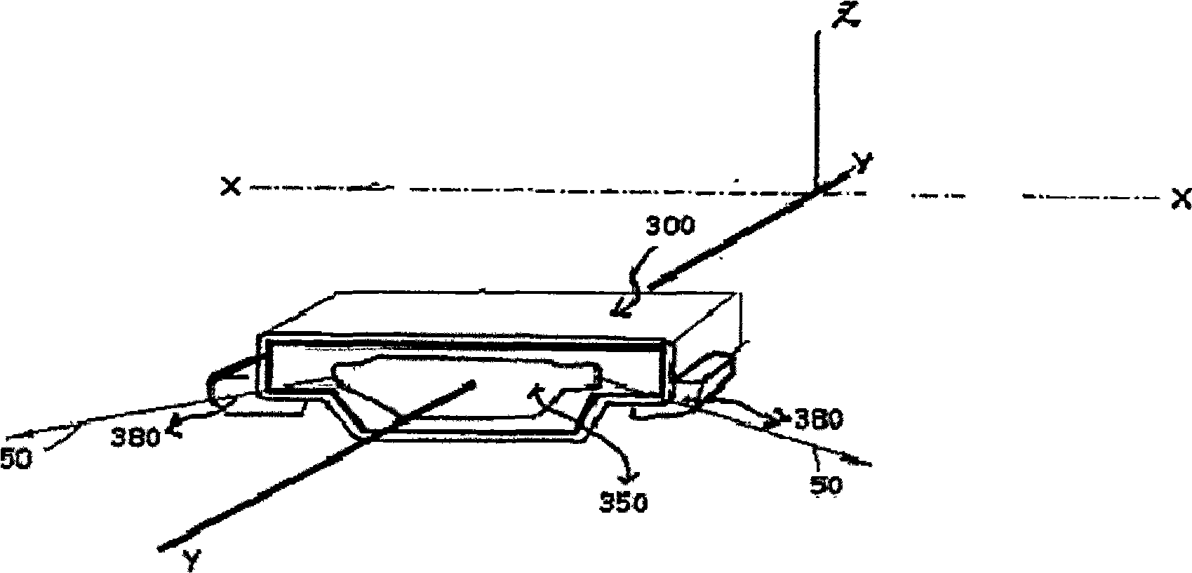
[0040] The experimental structure is the same as figure 1 As shown, 12 single-sided light emitting diodes 300 (each with a power of 0.125 watts, using the SWTS1007 series products of Seoul Semiconductor Corporation) are welded on a circuit board 400 to form a circular circle with a diameter of 30 mm. All the light-emitting surfaces 350 of the light-emitting diodes 300 face the reflector 500, and the reflector 500 is made of foamed polyethylene terephthalate of Furukawa Corporation. The current applied to the circuit board 400 was 0.135 amperes. The internal size of the reflector 500 is 900mm×900mm.

[0041] Placed on the reflector 500 is a diffuse transmissive translucent screen 68, which is model #432 of Shinkolite-A series from Mitsubishi Rayon Co. Ltd., with a thickness of 3mm and made of acrylic resin. The distance 62 between the light-transmitting screen 68 and the circuit board 400 is measured to be 35 mm.

[0042] The brightness on the translucent screen 68 is measur...


PUM


Abstract

The invention provides a uniform light-emitting device which comprises light-emitting diodes and a light-reflecting cover. Each light-emitting diode is a single-side light-emitting type light-emitting diode, and the light-reflecting cover is a diffused reflection light-reflecting cover. At least three single-side light-emitting type light-emitting diodes are arranged in a circle according to the shape of the light-reflecting cover in the light-reflecting cover, and the light-emitting faces of the light-emitting diodes face to the outside of the circle and are opposite to the light-reflecting cover. The direction position of the single-side light-emitting type light-emitting diodes is adjusted according to needed direction, and the single-side light-emitting type light-emitting diodes irradiate the light-reflecting cover with a proper distance and an incidence angle, then illumination of corresponding irradiated region on the light-reflecting cove is adjusted, and light irradiating the entire side wall of the light-reflecting cover is further more uniform. Meanwhile, colors corresponding to the light-emitting diodes are selected, the light-emitting intensity of various light-emitting diodes is controlled, and any required light color can be mixed. In addition, after the diffused reflection light-reflecting cover is adopted, light emitted by the light-emitting diodes irradiates the surface of the diffused reflection light-reflecting cover and is scattered completely, all of the light shines to a translucent screen, and the utilization rate of the light energy is high.

Description

technical field [0001] The invention belongs to a light emitting device, in particular to a uniform light emitting device using a light emitting diode as a light source. Background technique [0002] Luminous objects can attract people's attention. Businesses often use signboard light boxes to attract customers or advertise. Architects and lighting designers design luminous ceilings, luminous walls, and luminous facades of buildings based on this concept. The basic structure of this type of lighting system is to install a translucent light-transmitting screen on the front side of the light source to allow light to pass through the light-transmitting screen to create an elegant atmosphere, or to transmit images or information on the light-transmitting screen to people. . [0003] The above lighting systems usually use incandescent lamps, fluorescent lamps or neon lamps as light sources. As we all know, some of these light sources have low luminous efficiency, high power con...

Claims


Application Information

Patent Timeline
IPC IPC(8): F21V19/00F21V7/22F21Y101/02F21Y115/10
Inventor 洪志辉
Owner EDEE MARKETING
Why Eureka
Try Eureka