Air conditioner for humiture control

An air conditioner, temperature and humidity technology, used in air conditioning systems, space heating and ventilation, heating methods, etc., can solve the problems of high operating costs and high purchase costs, achieve a simple and compact structure, and solve the control, manufacture and production of temperature and humidity. The effect of running cost economy

Inactive Publication Date: 2009-08-05
张志耀
View PDF1 Cites 0 Cited by
  • Summary
  • Abstract
  • Description
  • Claims
  • Application Information

AI Technical Summary

Problems solved by technology

Although the configuration of this fresh air unit can solve the problem of temperature and humidity control, not only the purchase cost of the equipment is high, but also requires external installation, and the operating cost is also high

Method used


Image

  • Air conditioner for humiture control
  • Air conditioner for humiture control
  • Air conditioner for humiture control

Examples


Embodiment 1

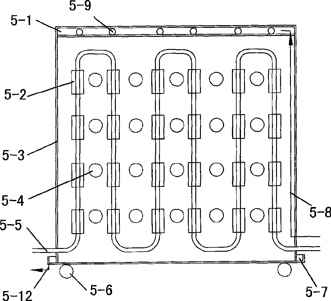
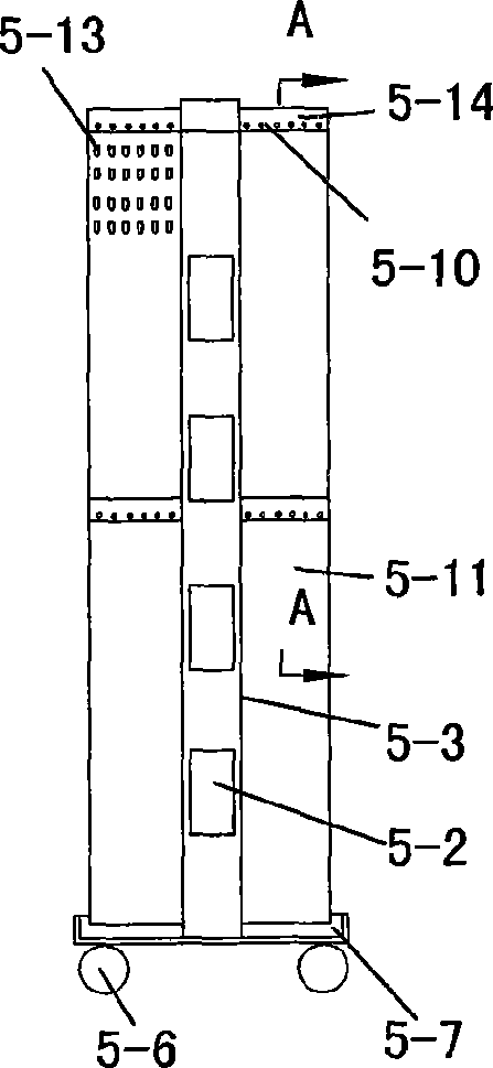
[0015] The temperature and humidity control air conditioner of the present embodiment is as follows: figure 1 , figure 2 and image 3 As shown, the box-type housing 5-3 is arranged along the zigzag cooling liquid pipe to fix the buckle 5-2 at intervals. The cross section of the buckle 5-2 is C-shaped, and the inner diameter matches the outer diameter of the cooling liquid pipe. The zigzag cooling liquid pipe 5-5 is clamped in each buckle 5-2 and fixed in the housing 5-3, and the space between the zigzag cooling liquid pipes 5-5 is provided with ventilation holes 5-4 distributed at intervals. The bottom of housing 5-3 is placed in the trough-shaped underframe 5-7, and the bottom of this trough-shaped underframe is equipped with roller 5-6. The top of the casing 5-3 is an overflow water storage chamber 5-1, and the water storage chamber is provided with overflow holes 5-9 distributed at intervals along both sides of the thickness direction of the casing 5-3. Water curtain pl...

Embodiment 2

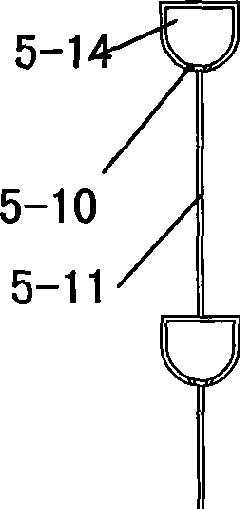
[0022] The basic structure of the temperature and humidity control air conditioner of this embodiment is the same as that of Embodiment 1, the difference is that the junction of the water curtain plate 5-11 and the housing 5-3 is hinged, and the overflow groove 5 at the top of the water curtain plate 5-11 -14 communicates with the overflow hole 5-9 of the overflow storage chamber 5-1 through a bendable connecting pipe. In this way, the water curtain can be folded up when necessary, so that the aisle in the room is spacious and convenient for work. In addition to the water curtain, foldable heat sinks can be added, and one end of the heat sink can even be lapped to the machine frame required for heat dissipation to enhance the heat transfer effect.

[0023] In addition to the above-mentioned embodiments, the present invention can also have other implementations. For example, the water curtain itself can also be folded, and foldable cooling fins can be added outside the water c...


PUM


Abstract

The invention relates to a temperature-humidity adjusting air conditioner, belonging to the technical field of air conditioner facilities. The air conditioner comprises a box type shell, circuit separating fixing buckles are arranged in the shell along a winding cooling liquid pipe, the sections of the buckles are of C shapes, and the inside diameters of the buckles are matched with the outside diameter of the cooling liquid pipe; the winding cooling liquid pipe is blocked in the buckles and fixed in the shell; the box type shell is provided with vent holes in the spaces of the cooling liquid pipe; the bottom of the shell is arranged in a groove-shaped chassis, and the top is provided with an overflow water accumulation chamber; the water accumulation chamber is provided with spaced overflow holes at two sides along the shell thickness direction; water curtain plates are arranged at intervals at the two sides along the shell thickness direction; the tops of the water curtain plates are fixed with overflow grooves respectively communicated with the overflow holes; and overflow holes are distributed at intervals at the abutting positions of the overflow grooves and water curtain plates. Compared with the prior art, the invention has simple and compact structure, can be arranged in a machinery room, has economical production and operation cost and can realize the adjustment and the control of both temperature and humidity.

Description

technical field [0001] The invention relates to an air conditioner, in particular to a temperature and humidity control air conditioner, which belongs to the technical field of air conditioners. Background technique [0002] At present, medium and large-scale computer rooms such as program-controlled switches and computers generally have the problems of uneven temperature and poor air conditioning effect. The reason is that the units are arranged in order, the air supply and cooling of the machine room, and the layout of the humidity adjustment system are not effective and reasonable. Preparation of corresponding air-conditioning facilities can certainly solve this type of problem, but the existing solutions are all too expensive. [0003] For example, the Chinese patent application with the application number 200810196559.0 discloses a fresh air unit, including a fan section, a flow equalization, a medium-efficiency and a sub-high-efficiency section, and a surface cooling,...

Claims


Application Information

Patent Timeline
Patent Type & Authority Applications(China)
IPC IPC(8): F24F1/04F24F5/00
CPCY02P80/10
Inventor 张志耀张啸
Owner 张志耀
Why Eureka
Try Eureka