Optical fiber connector

A technology of optical fiber connectors and fiber grooves, which is applied in the coupling of optical waveguides, etc., to achieve the effects of simple structure, reliable connection, and convenient installation

Inactive Publication Date: 2009-08-05
上海建宝光纤技术有限公司
View PDF2 Cites 20 Cited by
  • Summary
  • Abstract
  • Description
  • Claims
  • Application Information

AI Technical Summary

Problems solved by technology

The disadvantage of the above products is that the optical fiber c

Method used


Image

  • Optical fiber connector
  • Optical fiber connector
  • Optical fiber connector

Examples


Embodiment Construction

[0026] The present invention will be further described below in conjunction with the accompanying drawings.

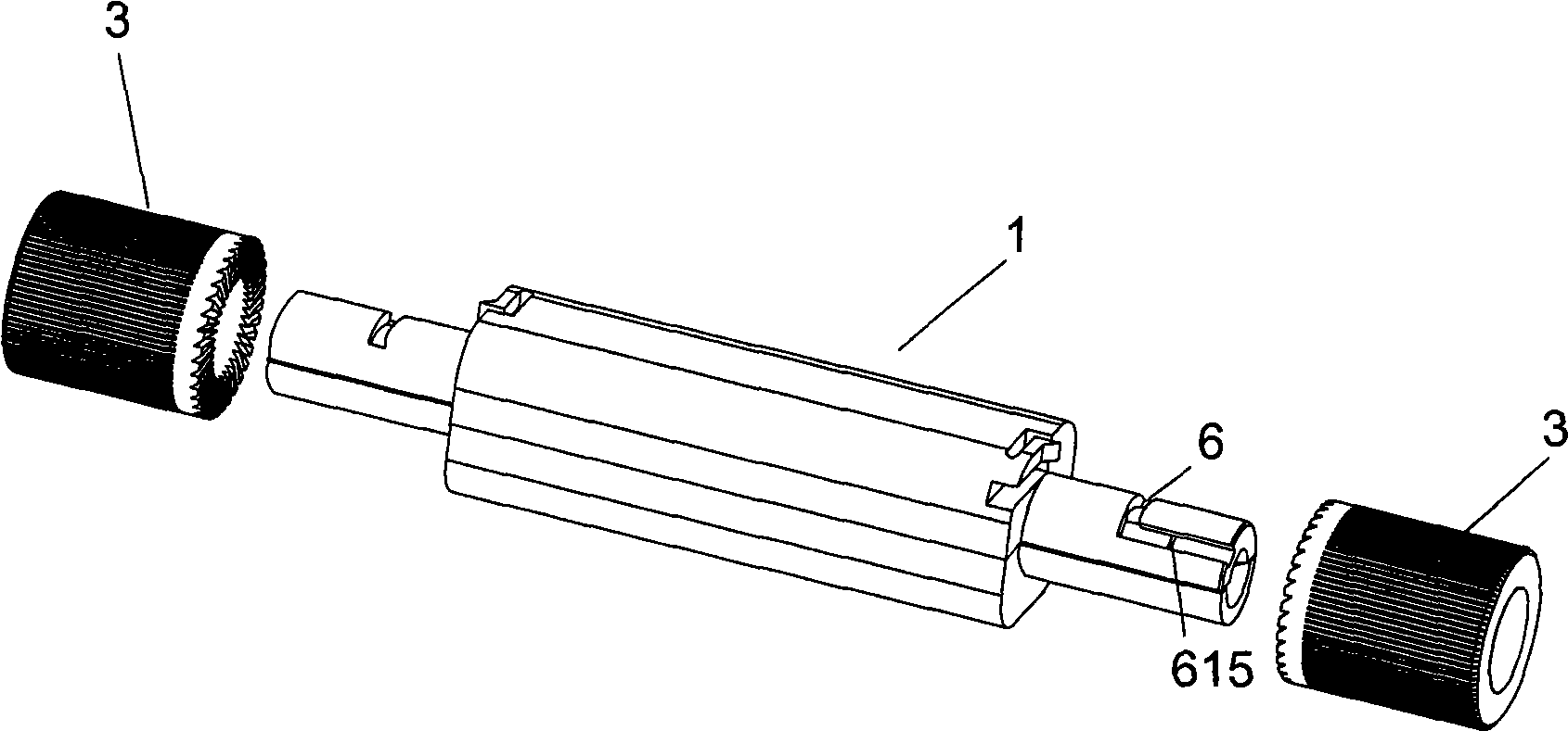
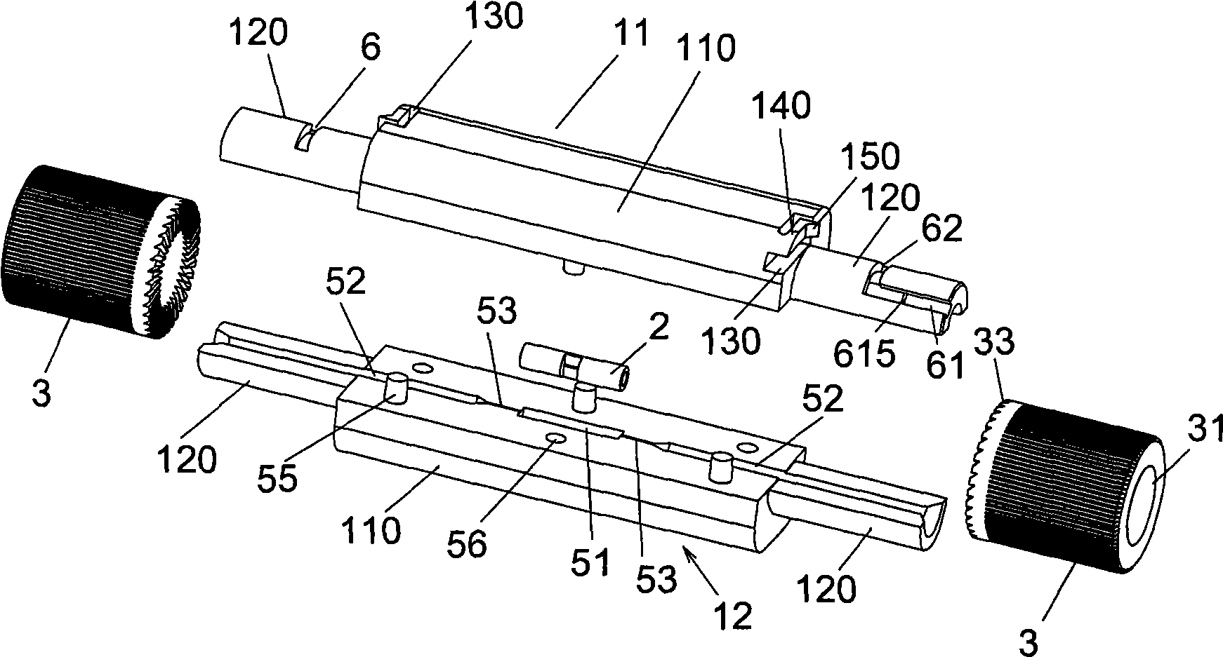
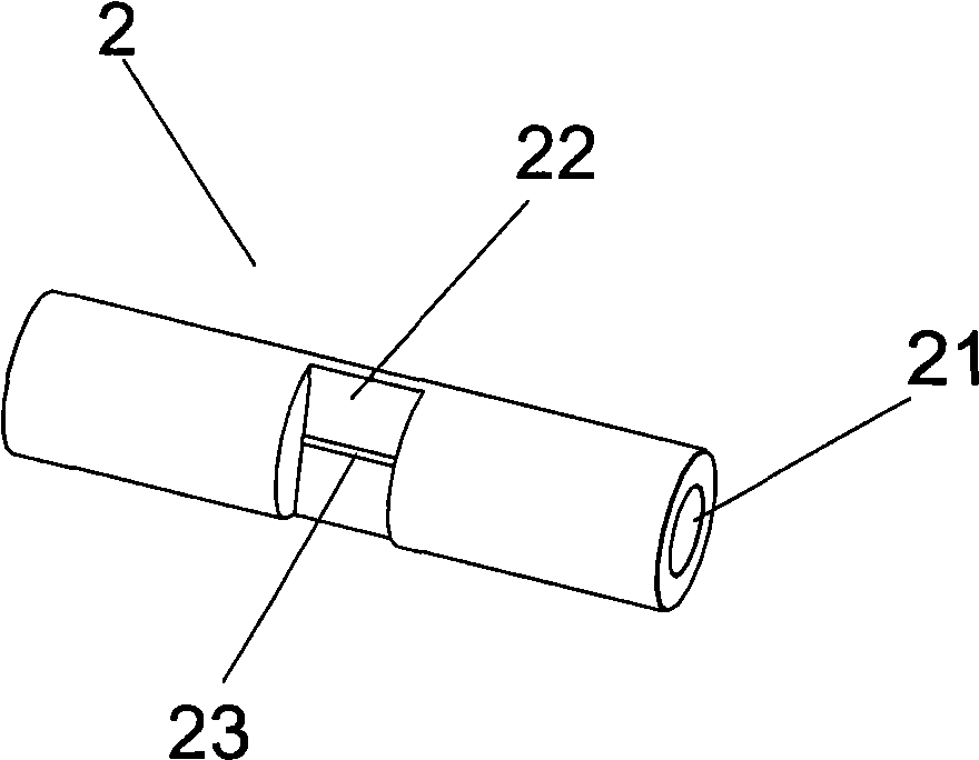
[0027] figure 1 and 2 The structure of the optical fiber splice according to the first embodiment of the present invention is shown. As shown in the figure, the optical fiber connector of the present invention includes a housing 1 , an optical fiber sleeve 2 and fixing sleeves 3 sleeved on both sides of the housing. The casing 1 includes an upper casing 11 and a lower casing 12, and the upper casing 11 and the lower casing 12 are superimposed on each other. The upper housing 11 and the lower housing 12 are symmetrically composed of a main body 110 and clamping parts 120 located on both sides of the main body 110, on the opposite sides of the main body 110 and the clamping part 120 of the upper and lower housings Fiber slots for accommodating optical fibers are arranged symmetrically. Figure 5 A schematic structural view of an optical fiber is shown, and the optica...


PUM


Abstract

The invention discloses an optical fiber continuous connection piece comprising a shell and an optical fiber bushing; the shell consists of an upper shell and a lower shell which are overlapped. An upper surface of the lower shell is provided with an optical fiber groove accommodating optical fibers; the optical fiber groove comprises a bushing groove for accommodating the optical fiber bushing and a guild groove part at the two sides of the bushing groove. The optical bushing is arranged in the bushing groove; a through hole is arranged in the center of the optical fiber bushing and is used for accommodating the optical fiber core; an outer wall of the optical fiber bushing is provided with a socket; an opening is arranged at the bottom of the socket and is communicated with the through hole; the width of the opening is less than the diameter of the optical fiber core. The optical fiber connection piece also comprises a plurality of clamps which are arranged at the two sides of the shell and are used for tightly clamping the upper shell and the lower shell. The invention adopts a metal optical fiber bushing as an alignment element for optical fibers, adopts a method of aligning first and then fixing to realize the continuous connection of optical fibers and has the advantages of simple structure, reliable continuous connection and not demanding special-used construction tools.

Description

technical field [0001] The invention relates to a device for mechanical optical fiber fixed connection. Background technique [0002] In the field of optical fiber communication, there are mainly two different ways to realize optical fiber splicing: fusion splicing and mechanical splicing. Mechanical optical fiber splicing, commonly known as optical fiber cold splicing, does not require a thermal fusion splicer, but only achieves permanent connection of optical fibers through mechanical connection technology and simple splicing tools. [0003] Among the existing mechanical optical fiber splicing devices, for example, the model of 3M Innovation Co., Ltd. in the United States is "FibrokII" mechanical optical fiber splicing son (disclosed on October 24, 2007, the domestic publication number is CN101061406A), and Belgian Tyco Electronics Rey The optical fiber mechanical splicing joint of Chemical Co., Ltd. (disclosed on January 12, 2005, domestic publication number is CN1564955...

Claims


Application Information

Patent Timeline
IPC IPC(8): G02B6/38
Inventor 张雯蕾
Owner 上海建宝光纤技术有限公司
Why Eureka
Try Eureka