Gas dispensing device and semiconductor process plant employing the same

A gas distribution and gas technology, applied in the field of microelectronics, can solve the problems of uneven distribution of plasma, uneven distribution of process gas, and influence on the uniformity of processing/treatment such as etching, etc., to achieve uniform plasma distribution, uniform distribution, Effect of Uniform Semiconductor Device Processing/Handling Results

Active Publication Date: 2009-08-05
BEIJING NAURA MICROELECTRONICS EQUIP CO LTD
View PDF0 Cites 35 Cited by
  • Summary
  • Abstract
  • Description
  • Claims
  • Application Information

AI Technical Summary

Problems solved by technology

[0015] Although the gas distribution device provided by prior art 1 can distribute gases such as process gases to enter the reaction chamber, in practical applications, it inevitably has defects such as uneven gas distribution.
This is because: the gas distribution device provided by prior art 1 has uneven gas distribution at the two inlet passages on the support plate, and the distance between the support plate and the choke assembly is relatively small, so that a gas flow is formed between the two. The height of the gas distribution chamber is also small, so that the gas entering the reaction chamber through the above two inlet channels has no time to diffuse evenly in the gas distribution chamber between the support plate and the choke assembly before entering the lower baffle Or the shower head electrode, so that the process gas that finally enters the reaction chamber through the shower head electrode is unevenly distributed, which leads to uneven distribution of the generated plasma, and finally affects the uniformity of etching and other processing / treatment sex

Method used


Image

  • Gas dispensing device and semiconductor process plant employing the same
  • Gas dispensing device and semiconductor process plant employing the same
  • Gas dispensing device and semiconductor process plant employing the same

Examples


no. 1 example

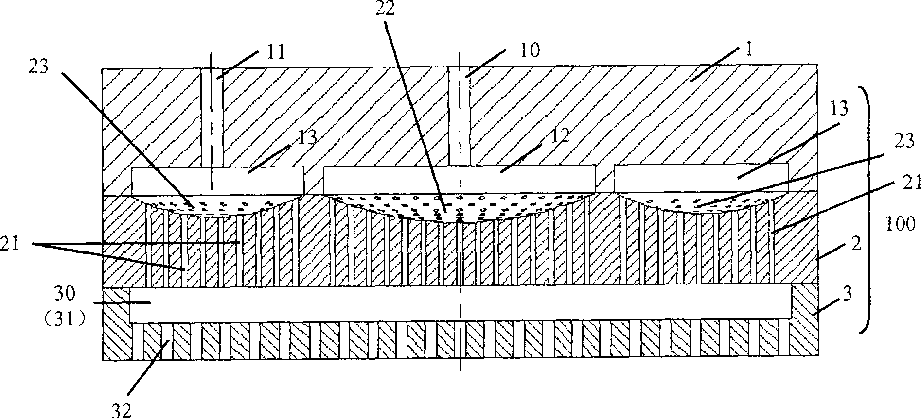
[0055]Similar to the first embodiment, the baffle 2 in this embodiment is also provided with a central concave area 22 of the baffle and an edge concave area 23 of the baffle on its upper surface. The difference from the first embodiment is that a recessed area is also provided on the lower surface of the baffle 2 corresponding to the concave area 22 in the center of the baffle and the concave area 23 on the edge of the baffle, that is, the flow baffle Plate central concave area 52 and baffle edge concave area 53, and a number of through holes 21 are set on the baffle 2, making it pass through the central concave area 22 and central concave area 52 on the baffle 2 , and through the edge concave region 23 and the edge concave region 53 on the spoiler 2, so that the process gas in the concave region (22, 23) is introduced into the concave region (52, 53), and here Diffusion further for a more even process gas distribution. In addition, similar to the spoiler central concave reg...


PUM


Abstract

The invention discloses a gas distribution device, comprising a supporting board, a spoiler and a spray header electrode, which are arranged in sequence in an overlapping way from top to bottom. An intake channel is arranged on the supporting board and an exhaust channel is arranged on the spray header electrode, wherein, at least one surface of the spoiler is provided with a spoiler concave part which is also provided with a through-hole for vertically running through the spoiler so as to lead the gas of the intake channel on the supporting board to be dispersed at the spoiler concave part, then transmitted to the spray header electrode by the through-hole, and later transmitted to a reaction cavity by the exhaust channel on the spray header electrode. In addition, the invention also discloses semiconductor processing equipment which uses the gas distribution device. The gas distribution device and the semiconductor processing equipment can distribute the gas such as process gas and the like to the inside of the reaction cavity uniformly, thus obtaining uniform distribution of the plasma and further even processing / dealing results.

Description

technical field [0001] The invention relates to the technical field of microelectronics, in particular to a gas distribution device and semiconductor processing equipment using the gas distribution device. Background technique [0002] With the rapid development of electronic technology, people have higher and higher requirements for the integration of integrated circuits, which requires companies that produce integrated circuits to continuously improve the processing / processing capabilities of semiconductor devices. Currently, plasma etching techniques are widely used in the processing / handling of semiconductor devices. The so-called plasma etching technology refers to the ionization of the process gas under the excitation of radio frequency power to form a plasma containing a large number of active particles such as electrons, ions, excited atoms, molecules and free radicals. Various physical and chemical reactions occur on the surface of an object (for example, a wafer) ...

Claims


Application Information

Patent Timeline
Patent Type & Authority Applications(China)
IPC IPC(8): H01L21/00H01L21/3065C23F4/00C23C16/455C30B25/14H01J37/32
Inventor 徐亚伟
Owner BEIJING NAURA MICROELECTRONICS EQUIP CO LTD
Why Eureka
Try Eureka