A/D conversion circuit and conversion method thereof
A conversion circuit and reference voltage source technology, applied in the direction of analog/digital conversion calibration/testing, physical parameter compensation/prevention, etc., can solve problems such as errors, and achieve the effects of improving accuracy, reducing errors, reducing zero drift and gain drift
- Summary
- Abstract
- Description
- Claims
- Application Information
AI Technical Summary
Problems solved by technology
Method used
Image
Examples
Embodiment
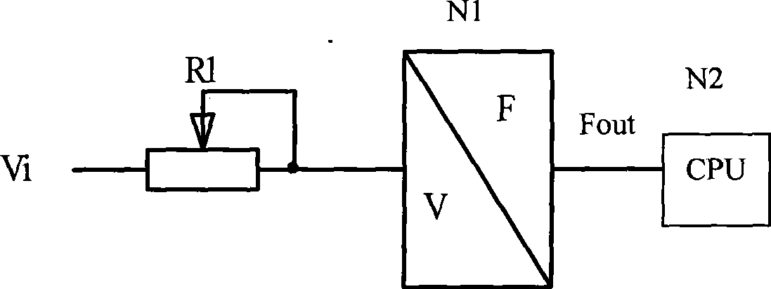
[0033] An A / D conversion circuit used in a data collector of a visibility meter, which includes a high-precision reference voltage source N1, a multi-selection-analog switch N2, a buffer amplifier N3, a charging resistor R1 and a V / F In the converter N4, the signal input terminal of the multi-choice analog switch N2 has n+2 input pins in total of S1, S2, S3, S4, ..., Sn+2, and it also has a control signal input terminal A and a The output pin D, the input pin S1 of the analog switch N2 is grounded, the input pin S2 is connected to the output end of the high-precision reference voltage source N1, and the input pins S3, S4, ..., Sn+2 are used for testing The voltage signal input terminals are respectively used to receive the analog voltage signals Vi1, Vi2, ... Vin to be tested, and its control signal input terminal A is connected to the control signal output terminal of the digital processor (CPU) N5 of the visibility meter, and its output pin D is sequentially connected to the...
PUM
 Abstract
Description
Claims
Application Information
 - R&D
- Intellectual Property
- Life Sciences
- Materials
- Tech Scout
- Unparalleled Data Quality
- Higher Quality Content
- 60% Fewer Hallucinations
Browse by: Latest US Patents, China's latest patents, Technical Efficacy Thesaurus, Application Domain, Technology Topic, Popular Technical Reports.
© 2025 PatSnap. All rights reserved.Legal|Privacy policy|Modern Slavery Act Transparency Statement|Sitemap|About US| Contact US: help@patsnap.com


