Door closer

A door closer and door leaf technology, used in door/window fittings, switches with brakes, wing leaf parts, etc., can solve the problems of high production costs, troublesome plunger installation, increased costs, etc., and achieve production costs. Reduced, simple-to-build effects

Inactive Publication Date: 2013-06-12
DORMA GMBH & CO KG
View PDF0 Cites 0 Cited by
  • Summary
  • Abstract
  • Description
  • Claims
  • Application Information

AI Technical Summary

Problems solved by technology

Proven disadvantage: It is very cumbersome to fit the plunger into the housing of the door closer
This leads to high production costs and thus a corresponding increase in costs

Method used


Image

  • Door closer
  • Door closer
  • Door closer

Examples


Embodiment Construction

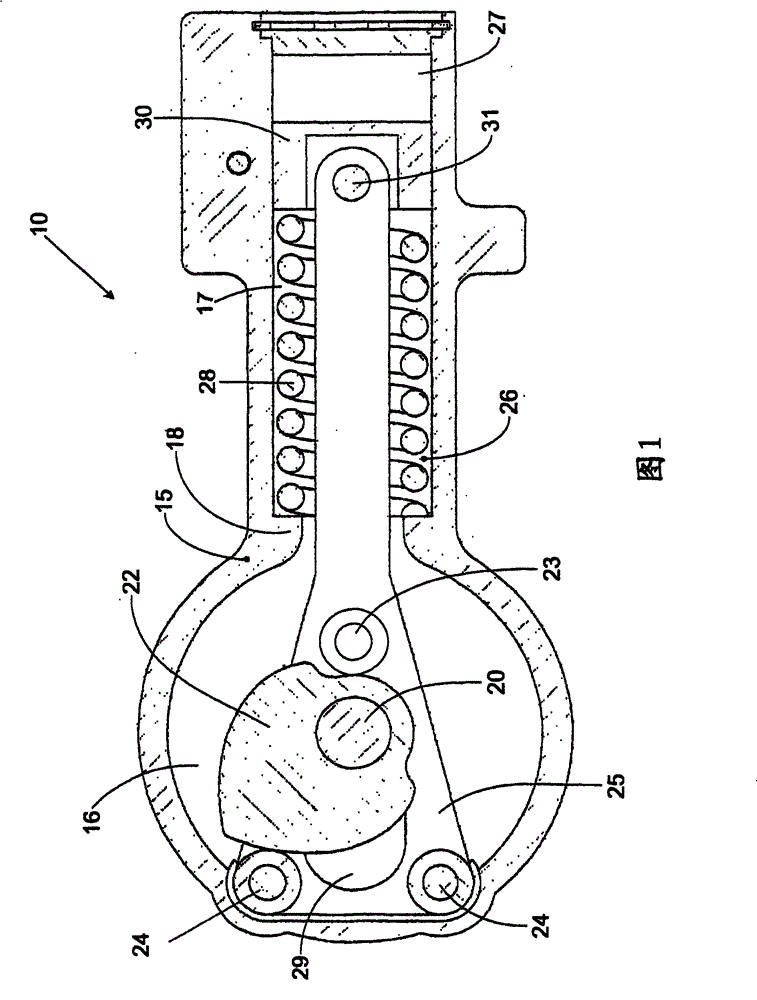
[0023] figure 1 A door closer 10 known from the prior art is shown in . The door closer 10 has a housing 15 in which a sliding plate carriage 25 is integrated. The plate carriage has a recess 29 through which a drive shaft 20 passes. The drive shaft 20 is connected to a (not shown) door leaf. Connected to the drive shaft 20 is a cam disc 22 designed in the shape of an eccentric. The connection can be a positive and / or non-positive connection. Movement of the door leaf causes rotation of the cam disc 22 . To convert the rotational movement into a translational movement, the cam disk 22 is arranged between three support or pressure means 23 , 24 . If the drive shaft 20 is rotated in the counterclockwise direction, the cam disc 22 is pressed against one of the pressure means 24 , which causes the slide carriage 25 to move into the front region 16 of the housing 15 .

[0024] The rear region 17 of the housing 15 is designed cylindrically. A spring 28 is mounted in the rear ...


PUM


Abstract

The invention relates to a door closer (10) with a driving spindle (20) which is mounted in a manner such that it can be connected to and rotated by a door wing, wherein the driving spindle (20) is connected within a housing (15) to a lifting cam disc (22) which is arranged between at least one supporting means (23) and at least one pressure means (24), wherein the supporting means (23) and the pressure means (24) are located on a tab carriage (25), a piston (30) for damping is arranged in the housing (15), and the piston (30) divides the housing (15), which is filled with a pressure medium, into two pressure spaces (26, 27) and is connected to the tab carriage (25) by a spring (28) which interacts firstly with the piston (30) and secondly with the housing (15), wherein the piston (30) has a coupling element (40) and an outer element (50), and the coupling element (40) is mounted in an at least partially form-fitting manner in a receptacle (51) of the outer element (50), and the receptacle (51) and an outer surface (41) of the coupling element (40) have grooves (42, 52), wherein a snap ring (60) connects the coupling element (40) and the outer element (50) and is at least partially arranged in the two grooves (42, 52) in such a manner that it is mounted inaccessibly within the piston (30).

Description

technical field [0001] The invention relates to a door closer. Background technique [0002] A door closer is known, for example, from EP756663B1 for professionals. A plate carriage (Laschenwagen) is integrated in the housing of the door closer, which serves as a rotation / translation converter. The basis used is a cam disc in the form of an eccentric, which can be set in rotation by the movement of the door leaf. The plate carriage has a support roller and a pressure roller, between which the cam disc is arranged in a force-locking manner. In this way, the rotational movement of the cam disc results in a translational movement of the plate carriage. Depending on the direction of the translational movement, this translation leads to the charging of an energy accumulator such as a spring. The stored energy causes the return movement of the plate carriage, which causes the rotation of the cam disc and the drive shaft connected to it. This rotational movement is used for th...

Claims


Application Information

Patent Timeline
Patent Type & Authority Patents(China)
IPC IPC(8): E05F3/10
CPCE05Y2800/26E05Y2201/456E05Y2600/53E05Y2201/256E05F3/104E05Y2201/264E05Y2800/00E05Y2900/132E05Y2800/20E05Y2800/205
Inventor T·武勃兰特
Owner DORMA GMBH & CO KG
Why Eureka
Try Eureka