
Combustion controller for stoker type incinerator

A control device and technology for incinerators, applied in incinerators, combustion methods, combustion types, etc., can solve problems such as undisclosed mixing ratio control

Active Publication Date: 2011-07-27
MITSUBISHI HEAVY IND LTD +1
View PDF1 Cites 0 Cited by
  • Summary
  • Abstract
  • Description
  • Claims
  • Application Information

AI Technical Summary

Problems solved by technology

[0012] However, in the above-mentioned prior application invention, the proposal is limited to the mixing of recirculated gas and air (primary air and secondary air for combustion) in the above-mentioned charging type incinerator and the method of returning to the incinerator side, and the method for The device for performing such mixing and recirculation to the incinerator side does not disclose the specific mixing ratio control of the recirculation gas and air that are recirculated to the incinerator side, or the recirculation of the air-mixed recirculation gas in the above-mentioned prior application invention. Combustion control in the incinerator, etc.

Method used


Image

  • Combustion controller for stoker type incinerator
  • Combustion controller for stoker type incinerator
  • Combustion controller for stoker type incinerator

Examples


no. 1 approach

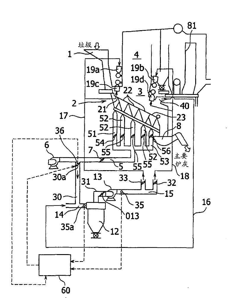
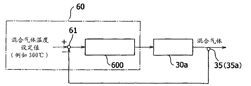
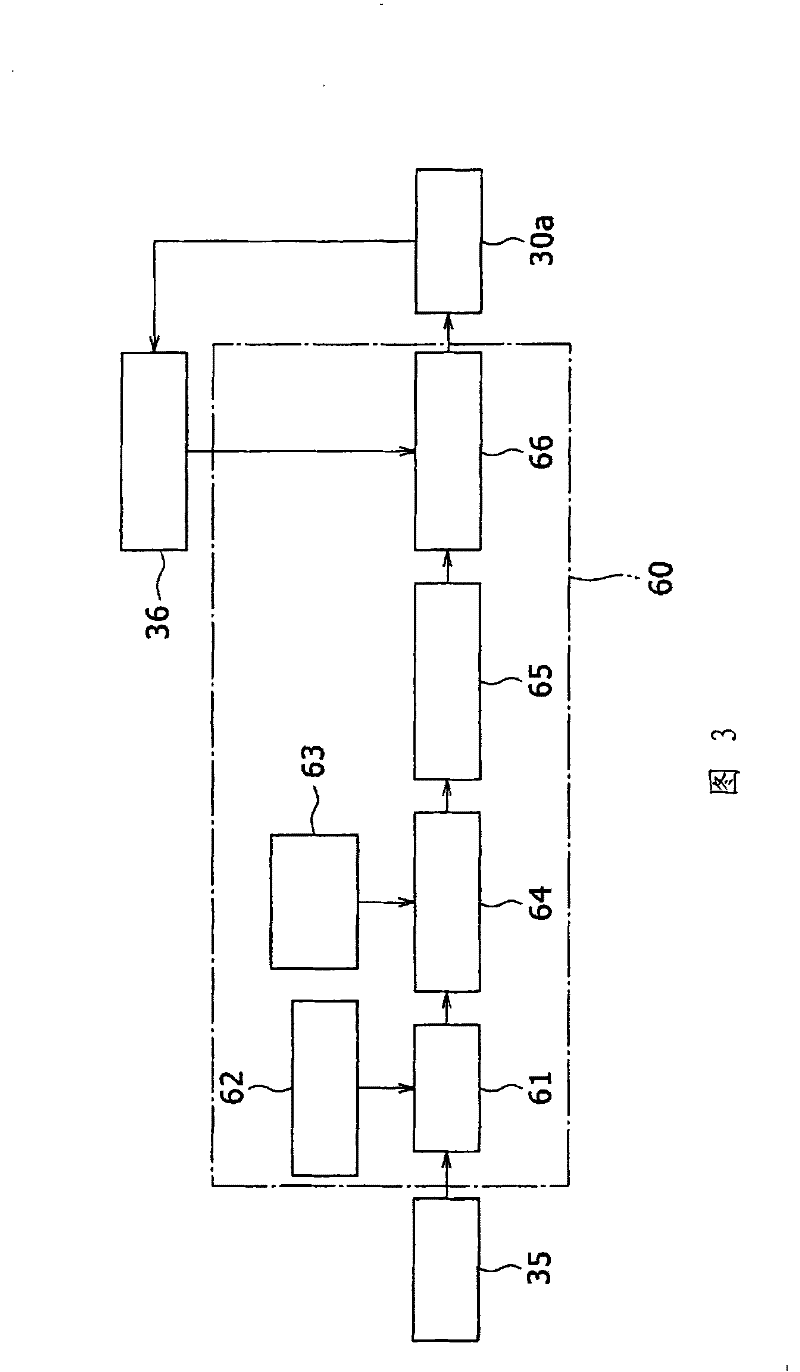
[0043] figure 1 It is a block diagram showing the charging type incinerator according to the first embodiment of the present invention, figure 2 is a schematic configuration diagram showing the combustion control device of the above-mentioned first embodiment, image 3 It is a combustion control block diagram of the above-mentioned first embodiment.

[0044] figure 1 In the figure, reference numeral 1 is a garbage hopper into which to-be-incinerated materials such as garbage and industrial waste are thrown, and reference numeral 2 is a charging type incinerator. The charging type incinerator 2 is laid with: a drying area feeder 21 mainly constituting the drying area at the bottom of the furnace from the input port of the garbage hopper 1, a main combustion area feeder 22 mainly constituting the combustion area, and an ember mainly constituting Ember combustion zone feeder 23 in the combustion zone. The feeder 21 in the drying zone is located on the most upstream side, the...


PUM


Abstract

A combustion control unit for stoker-fired combustion furnace including air flow rate regulating means (30a) for regulating of the rate of air flow to air flow channel (30); temperature detecting means 35(35a) for detecting of the temperature of air-mixed recirculating gas; and combustion control means (60) adapted to have the value of detected temperature of air-mixed recirculating gas inputted from the temperature detecting means 35(35a), to compute, on the basis of the value of detected temperature, the area of flow channel of air flow rate regulating means (36) allowing the temperature ofair-mixed recirculating gas to become a preset target temperature and to control the flow rate regulating means (36) at the value of flow channel area computed.

Description

technical field [0001] The present invention relates to a combustion control device for a charging type incinerator. The primary air is introduced from the bottom of a feeder for inputting garbage, industrial waste, etc. The upper portion of the combustion chamber performs secondary combustion. Background technique [0002] The feeding type (スト一カ) incinerator is an incinerator configured as follows. It is equipped with a feeder configured by alternately arranging the grate of the fixed section and the movable section. While stirring and advancing the garbage (incinerated materials) put into the hopper, the garbage is dried in the drying zone arranged on the upstream side of the feeder, and the primary air is injected into the next main combustion zone, and the main combustion is carried out, and the most downstream The ember burning area on the side burns the remaining amount of embers. [0003] Patent Document 1 (Japanese Patent No. 3582710) provides a technique in which,...

Claims


Application Information

Patent Timeline
Patent Type & Authority Patents(China)
IPC IPC(8): F23G5/50F23G5/14F23G5/44
CPCF23G5/50F23G5/14F23G5/44
Inventor 马渡匡之田熊昌夫常泉慎也山内恒树
Owner MITSUBISHI HEAVY IND LTD
Learn More