Electric rotating machine
A technology for rotating electrical machines and stator cores, applied in synchronous generators, electromechanical devices, electrical components, etc., can solve problems such as stator coil heat dissipation and stator, and achieve the effects of suppressing poor insulation, suppressing temperature rise, and suppressing the increase of reluctance Effect
- Summary
- Abstract
- Description
- Claims
- Application Information
AI Technical Summary
Problems solved by technology
Method used
Image
Examples
Embodiment approach 1
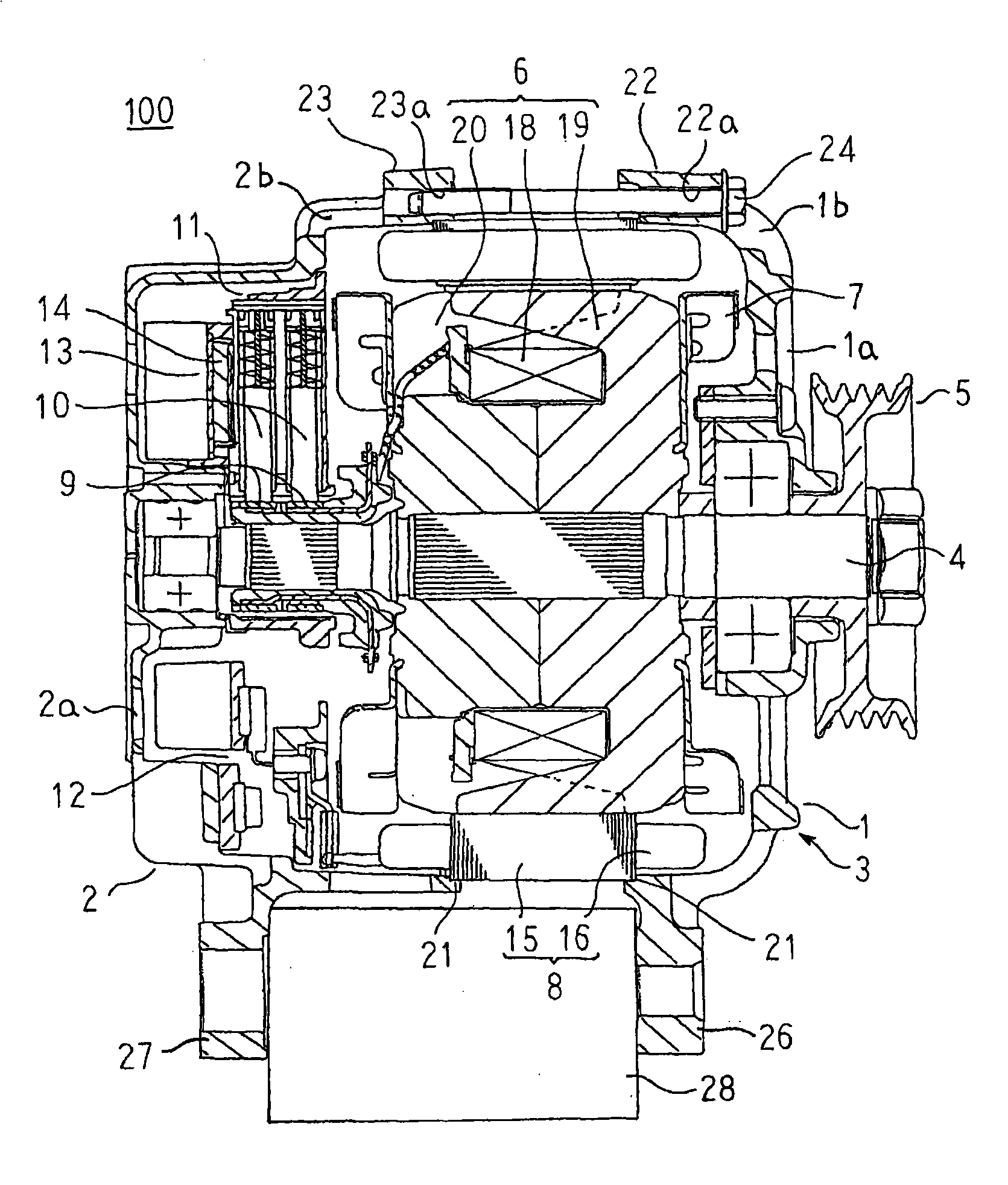
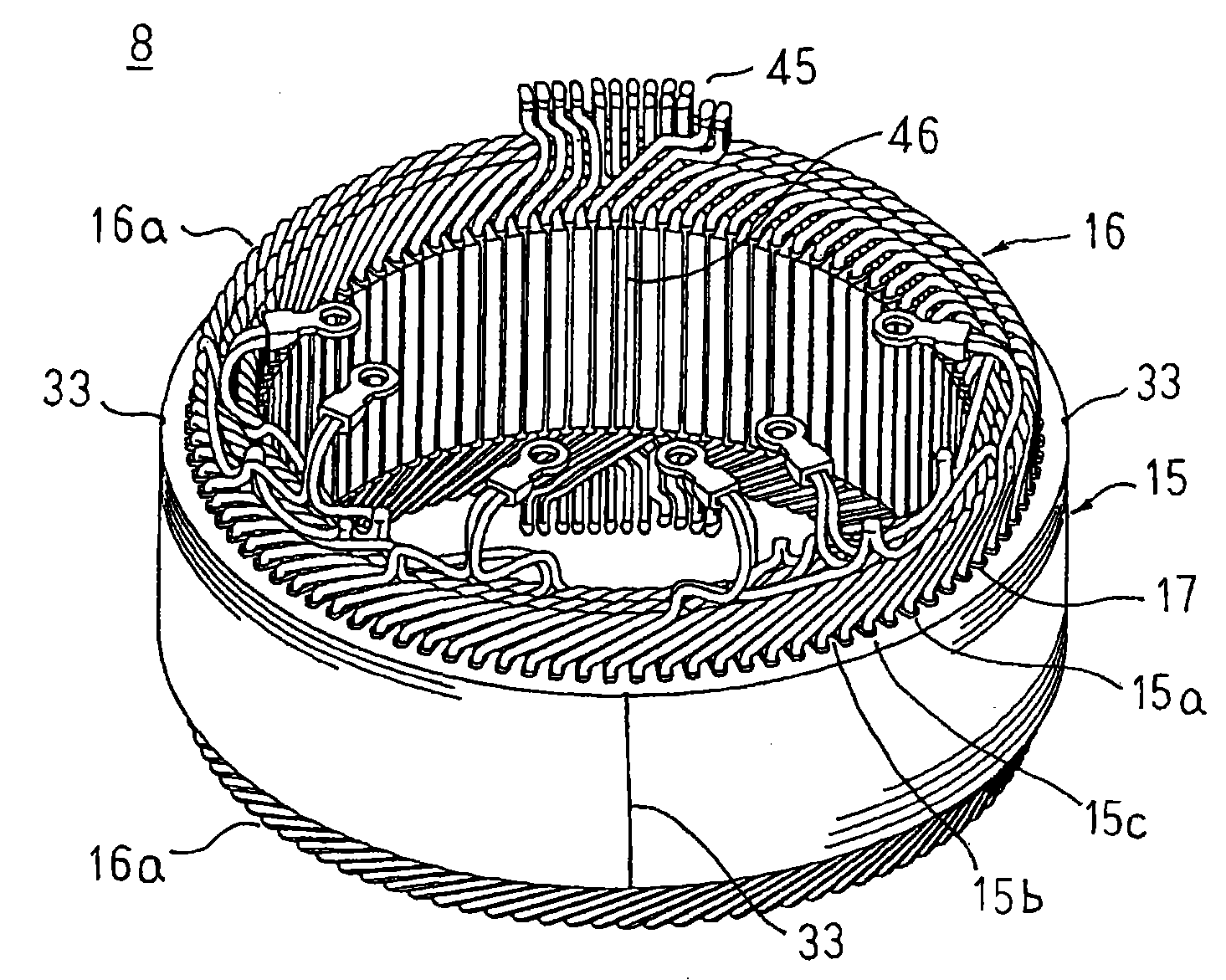
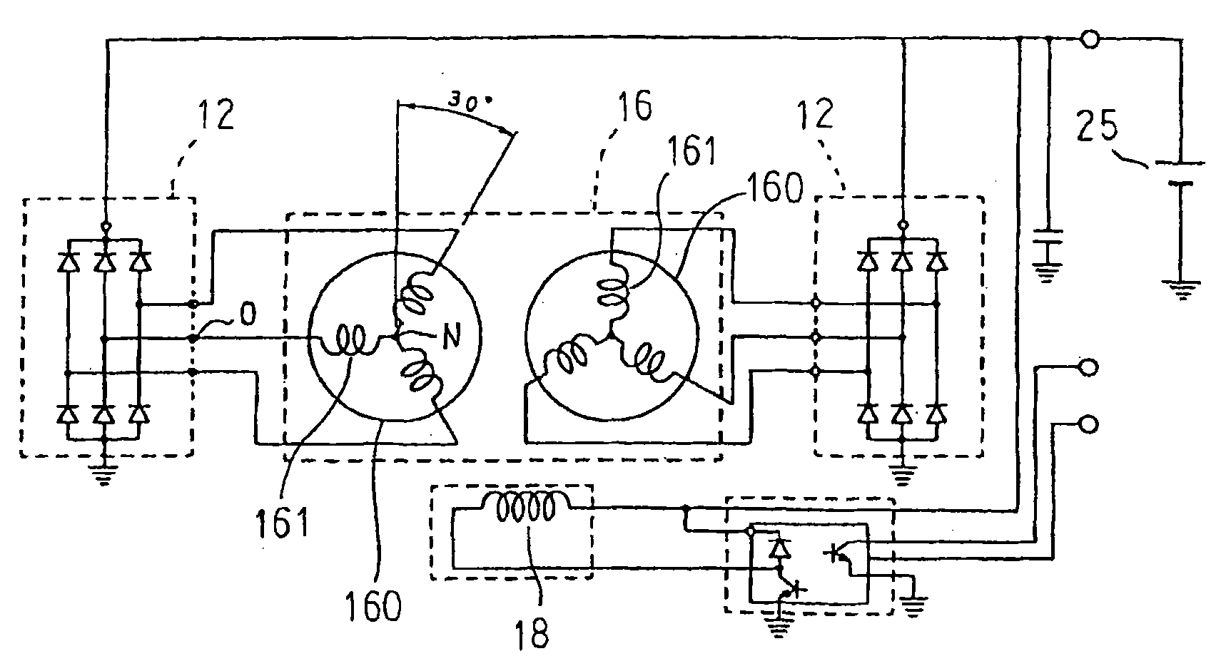
[0028] figure 1 is a longitudinal sectional view showing the automotive alternator according to Embodiment 1 of the present invention, figure 2 is a perspective view showing a stator applied to an automotive alternator according to Embodiment 1 of the present invention, image 3 is a circuit diagram showing an automotive alternator according to Embodiment 1 of the present invention, Figure 4 It is a cross-sectional view of main parts for explaining the fixing structure of the stator of the automotive alternator according to Embodiment 1 of the present invention.
[0029] exist Figure 1 to Figure 4 Among them, the vehicle alternator 100 includes: a casing 3, which is composed of a front frame 1 and a rear frame 2 that are made of aluminum and are approximately cup-shaped, respectively; 4; a pulley 5 affixed to the end of the shaft 4 extending toward the front side of the casing 3; a rotor 6 fixed on the shaft 4 and housed in the casing 3; fixed on both axial ends of the r...
Embodiment approach 2
[0053] Figure 12 It is a cross-sectional view of main parts for explaining the fixing structure of the stator of the automotive alternator according to Embodiment 2 of the present invention.
[0054] exist Figure 12 In , the insulating film 29 covers the outer peripheral surface of the stator core 15 .
[0055] The other structures are the same as those of the first embodiment described above.
[0056] In Embodiment 2, as in Embodiment 1 above, strip-shaped magnetic thin plates 31 are laminated and integrated to form a rectangular parallelepiped laminated core 32, and the laminated core 32 to which winding assembly 40 is attached is bent into a cylindrical shape, and the The stator core 15 is formed by abutting and welding both end faces of the laminated core 34 bent into a cylindrical shape. Next, an insulating resin made of, for example, an epoxy resin is applied to the outer peripheral surface of the stator core 15 to form the stator core 15 in which the insulating fil...
Embodiment approach 3
[0061] Figure 13 It is a cross-sectional view of main parts for explaining the fixing structure of the stator of the automotive alternator according to Embodiment 3 of the present invention.
[0062] exist Figure 13 Among them, the stator core 15A is produced by laminating a predetermined number of strip-shaped magnetic thin plates 31 having a thickness (t1) of 0.3 mm, for example, and laminating a strip-shaped magnetic thin plate 31A having a thickness (t2) of 1.0 mm, for example. Both ends of the laminate of strip-shaped magnetic thin plates 31 are formed by welding the laminates of strip-shaped magnetic thin plates 31, 31A into one body, bending them into a cylindrical shape, and welding the butt joints of both ends.
[0063] The other structures are the same as those of the first embodiment described above.
[0064] In Embodiment 3, since the strip-shaped magnetic thin plates 31A made of thick plates are arranged at both ends of the laminated body bent into a cylindric...
PUM
 Abstract
Description
Claims
Application Information
 - R&D
- Intellectual Property
- Life Sciences
- Materials
- Tech Scout
- Unparalleled Data Quality
- Higher Quality Content
- 60% Fewer Hallucinations
Browse by: Latest US Patents, China's latest patents, Technical Efficacy Thesaurus, Application Domain, Technology Topic, Popular Technical Reports.
© 2025 PatSnap. All rights reserved.Legal|Privacy policy|Modern Slavery Act Transparency Statement|Sitemap|About US| Contact US: help@patsnap.com


