Horizontal evacuating device

A vacuum device, horizontal technology, applied in the direction of non-volume pumps, machines/engines, mechanical equipment, etc., can solve the problems of large head of the circulation mechanism, shutdown for maintenance, accumulation of dirt in the nozzle tube 3, etc., to achieve location selection Reasonable, adaptable, and the effect of reducing head

Inactive Publication Date: 2009-08-12
江苏天泽新材料有限公司
View PDF0 Cites 2 Cited by
  • Summary
  • Abstract
  • Description
  • Claims
  • Application Information

AI Technical Summary

Problems solved by technology

[0003] One of the shortcomings of the vacuum device with the above structure is that since the nozzle pipe 3 is placed on the support 31, the head of the circulation mechanism is large, and the electric energy consumed by the motor 21 is large, which is not conducive to energy saving; During the production process of chemical and pharmaceutical products, the water in the water tank 1 is usually acidic, because the vacuum connecting pipe 5 will inevitably bring out the acidic substances in the production process, so the corrosion of the bracket 31 is very serious, and it needs to be replaced without multiple times. Affect the normal progress of production; third, connect the vacuum nozzle 5 directly to the nozzle pipe 3, which is easy to accumulate dirt in the nozzle pipe 3, thereby affecting the vacuuming effect at the slightest, and the nozzle pipe 3 needs to be replaced in time if it is serious, resulting in Shut down for maintenance, affecting production; Fourth, the nozzle tube 3 is supported by the bracket 31, which increases the height of the entire vacuum device, which makes installation difficult in some places where the space is limited, that is, it is picky about the installation site

Method used


Image

  • Horizontal evacuating device
  • Horizontal evacuating device

Examples


Embodiment Construction

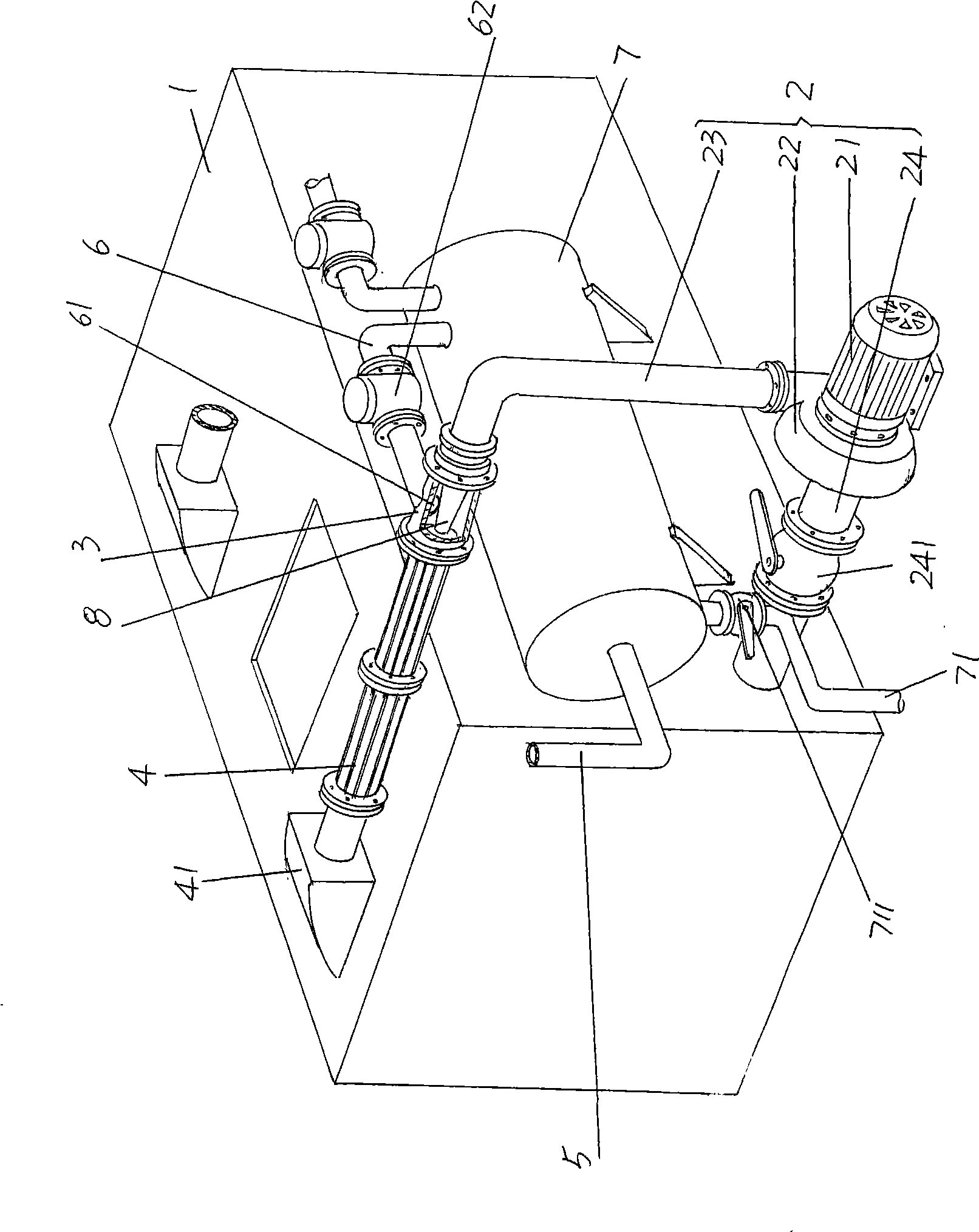
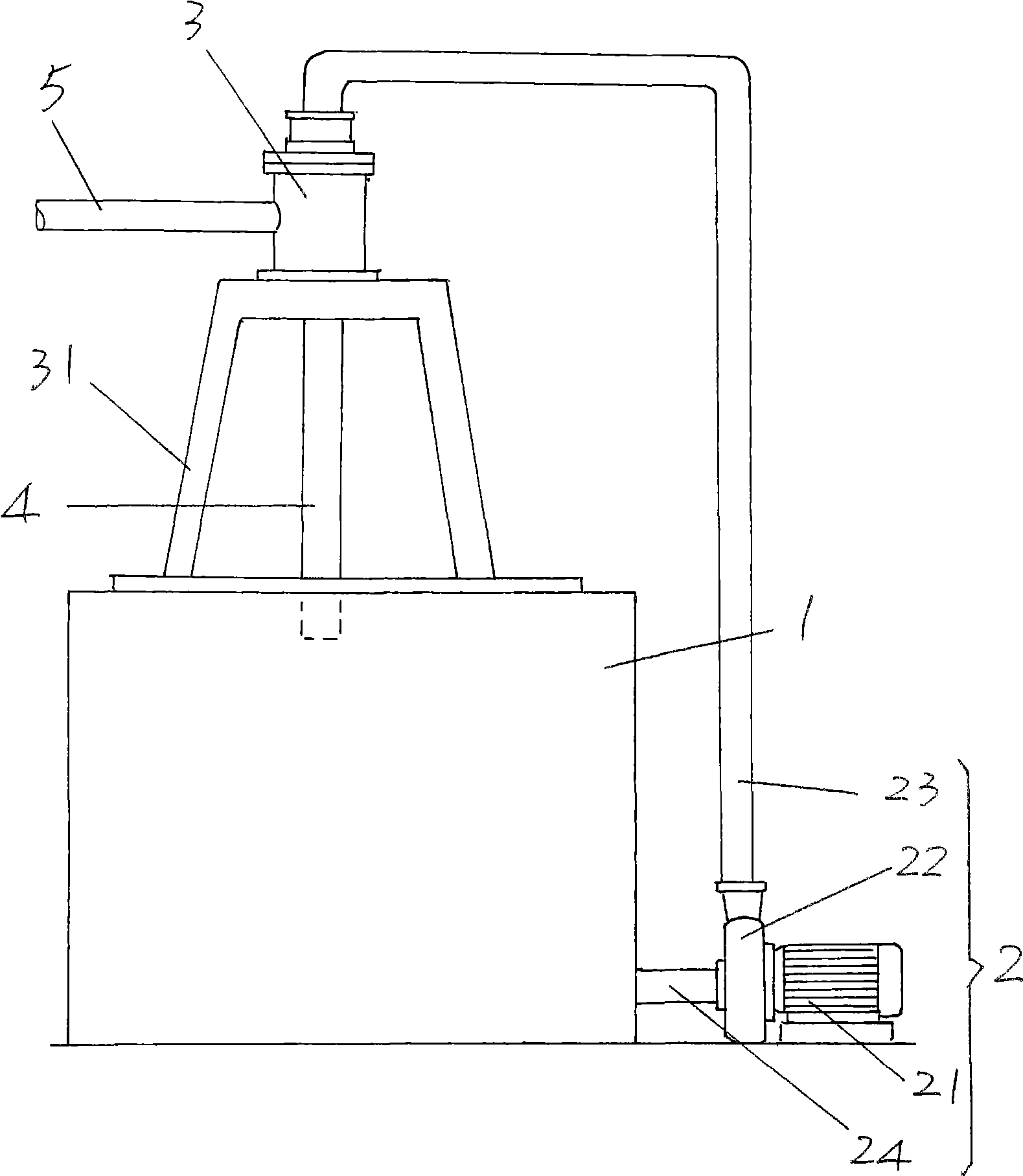
[0014] please see figure 1 , a rectangular water tank 1 is provided, more specifically a cuboid water tank 1 is provided, and the tank body 1 is made of a non-metallic material with good acid resistance. One end of the water inlet pipe 24 of the water circulation mechanism 2 connected in series between the water tank 1 and the nozzle pipe 3 is connected to the water tank 1, and the other end is connected to the water inlet of the water pump 22. The water pump 22 is matched with the motor 21, and one end of the water outlet pipe 23 It is connected with the water outlet of the water pump 22, and the other end is connected with the nozzle pipe 3. In the nozzle pipe 3, a nozzle 8 is provided. The water inlet of the nozzle 8 is connected to the water outlet pipe 23 through a flange and communicated with each other. One end of the connecting pipe 6 on the upper side of the nozzle pipe 3, the other end of the connecting pipe 6 is connected with the vacuum tank 7, and a valve 62 is ...


PUM


Abstract

The invention relates to a horizontal vacuuming device, which belongs to the technical field of negative pressure generating devices in production of chemical products. The horizontal vacuuming device comprises a water tank, a water circulation mechanism, a spray head pipe, a return pipe and a vacuum connecting pipe, wherein the water circulation mechanism comprises a motor, a water pump matched with the motor, and water inlet and outlet pipes; one end of the water inlet pipe is connected with the water tank, while the other end is connected with a water inlet of the water pump; one end of the water outlet pipe is connected with a water outlet of the water pump, while the other end is connected with the spray head pipe; and one end of the return pipe is connected with the spray head pipe, while the other end is connected with the water tank. The horizontal vacuuming device is characterized in that the side part of the water tank is provided with a vacuum tank, the vacuum connecting pipe is connected with the vacuum tank, the side part of the spray head pipe is connected with one end of a connecting pipe, the other end of the connecting pipe is connected with the vacuum tank, an air suction opening of the connecting pipe is communicated with a pipe cavity of the spray head pipe, and the return pipe is horizontally connected with the spray head pipe and the water tank respectively. The horizontal vacuuming device has the advantages that the delivery lift can be reduced, the pipeline can be shortened, energy saving can be achieved, the structure is reasonable, the spray head pipe can be not to be attacked by pollutants, the adaptability to a mounting place is strong.

Description

technical field [0001] The invention belongs to the technical field of negative pressure generating devices in the production of chemical products, and in particular relates to a horizontal vacuum pumping device. Background technique [0002] The structure of the vacuum device used in the prior art is as figure 2 As shown, it includes a water tank 1, a water circulation mechanism 2, a nozzle pipe 3, a water return pipe 4 and a vacuum connection pipe 5. The water circulation mechanism 2 includes a motor 21, a water pump 22 and inlet and outlet pipes 24, 23, and the motor 21 is connected with the water pump 22. One end of the water pipe 24 is connected with the water tank 1 and communicated with the water tank 1, the other end is connected with the water inlet of the water pump 22, one end of the water outlet pipe 23 is connected with the water outlet of the water pump 22, and the other end is connected with the nozzle pipe 3, and the nozzle pipe 3 is installed on On a suppor...

Claims


Application Information

Patent Timeline
Patent Type & Authority Applications(China)
IPC IPC(8): F04F5/04F04F5/52
Inventor 谭建平王俊华
Owner 江苏天泽新材料有限公司
Why Eureka
Try Eureka