Air-supporting slide rail system

An air flotation guide and air flotation technology, which is applied to valve devices, valve details, engine components, etc., can solve the problems of easily blocking air flotation holes and easily causing accidents, and achieves the effect of small air film vibration.

Active Publication Date: 2009-08-12
SHANGHAI MICRO ELECTRONICS EQUIP (GRP) CO LTD +1
View PDF4 Cites 10 Cited by
  • Summary
  • Abstract
  • Description
  • Claims
  • Application Information

AI Technical Summary

Problems solved by technology

[0009] When a small air flotation hole diameter is used in engineering practice, the Reynolds number has been reduced to below 2000. When it is

Method used


Image

  • Air-supporting slide rail system
  • Air-supporting slide rail system

Examples


Embodiment Construction

[0022] In order to make the object, technical solution and advantages of the present invention clearer, the present invention will be further described in detail below in conjunction with the accompanying drawings.

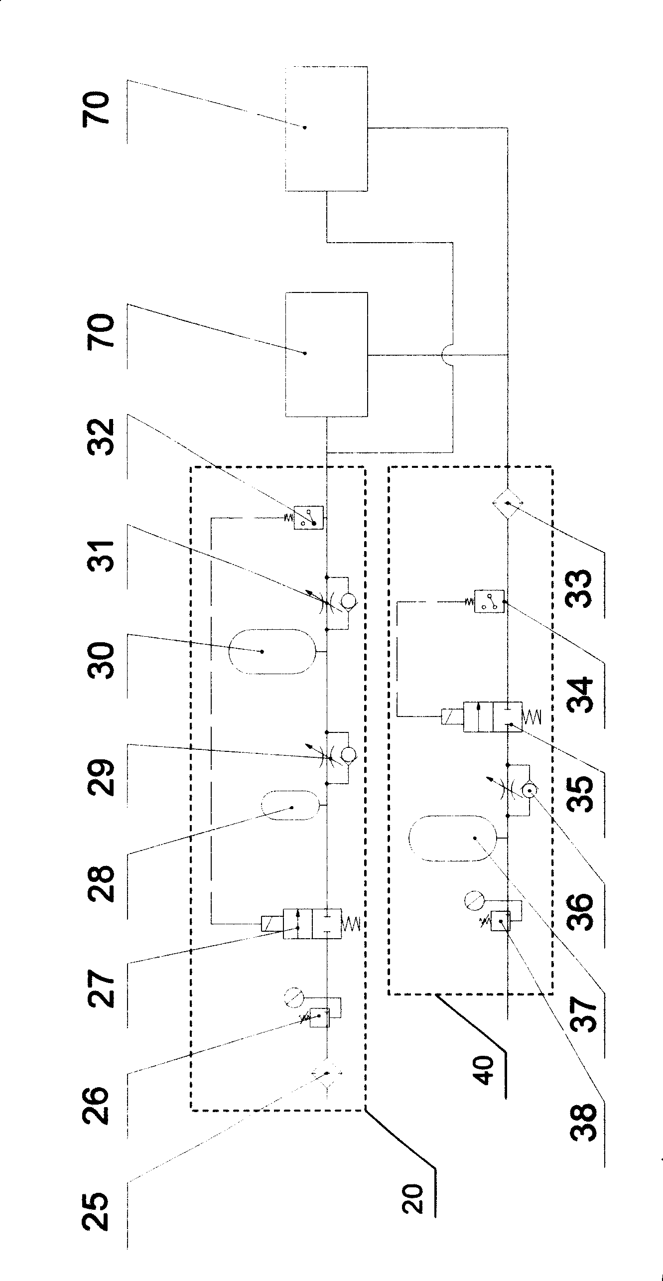
[0023] figure 1 Shown is a schematic structural diagram of an embodiment of the air-floating rail system provided by the present invention. like figure 1As shown, the air bearing rail system includes a compressed air control air circuit 20 , a vacuum control air circuit 40 and two air bearing rails 70 . The compressed air control air circuit 20 and the vacuum control air circuit 40 can supply air to one or more air bearing guide rails at the same time. In this embodiment, to supply air to two air bearing guide rails simultaneously, the structural parameters of the two air bearing guide rails exactly the same. The compressed air control air circuit 20 includes a filter 25, a precision pressure regulating valve 26, a first solenoid valve 27, two first constant pr...


PUM


Abstract

The invention relates to an air-float guide rail system, which belongs to the field of precision instruments. The air-float guide rail system comprises a compressed air control air circuit, a vacuum control air circuit and an air-float guide rail, wherein the air-float guide rail comprises an air-float area and a vacuum cavity; the compressed air control air circuit comprises a first constant pressure air bag for supplementing air for the air-float area of the air-float guide rail; and the vacuum control air circuit comprises a second constant pressure air bag for extracting the air in the vacuum cavity of the air-float guide rail. The air-float guide rail system has the characteristic of small air film vibration.

Description

technical field [0001] The invention belongs to the field of precision instruments, and in particular relates to an air flotation guide rail system including a compressed air control air path and a vacuum control air path. Background technique [0002] The ultra-precision air-floating workpiece table system is the core subsystem of the current mainstream lithography machine, which requires nano-level repeat positioning accuracy and synchronous motion accuracy. Since the accuracy of the air bearing guideway system is two orders of magnitude higher than that of the ball linear guideway, it has the advantages of high precision, low friction, and long life, and meets the requirements of high precision, high stability, and high speed. The air bearing guideway structure is used in ultra-precision workpiece tables. widely used in the system. However, in the application, it is found that the air bearing guide rail will have a slight vibration with an amplitude of nanometers, and th...

Claims


Application Information

Patent Timeline
IPC IPC(8): G03F7/20F16K31/02
Inventor 李生强齐芊枫张锋
Owner SHANGHAI MICRO ELECTRONICS EQUIP (GRP) CO LTD
Why Eureka
Try Eureka