Servobrake

A technology of amplifier and braking force, which is applied in the direction of brakes, braking transmissions, transportation and packaging, etc., and can solve problems such as annoying noise, response of brake force amplifier and adverse effects on release time dynamic performance

Inactive Publication Date: 2009-08-12
CONTINENTAL TEVES AG & CO OHG
View PDF1 Cites 9 Cited by
  • Summary
  • Abstract
  • Description
  • Claims
  • Application Information

AI Technical Summary

Problems solved by technology

However, in the known brake booster, annoying noises occur during normal operation. This unfavorable noise characteristic is due to the sudden deflection of the air flow at the edge of the sleeve and due to the unilateral lifting of the second sealing seat from the valve body. The inflowing air flow will vortex towards the working chamber at the second sealing seat, and the vortex will cause a vibrating air column in a cavity of the valve body
Second, also seen as a disadvantage, eddy currents have a detrimental effect on the response and release time dynamics of the brake booster

Method used


Image

  • Servobrake
  • Servobrake
  • Servobrake

Examples


Embodiment Construction

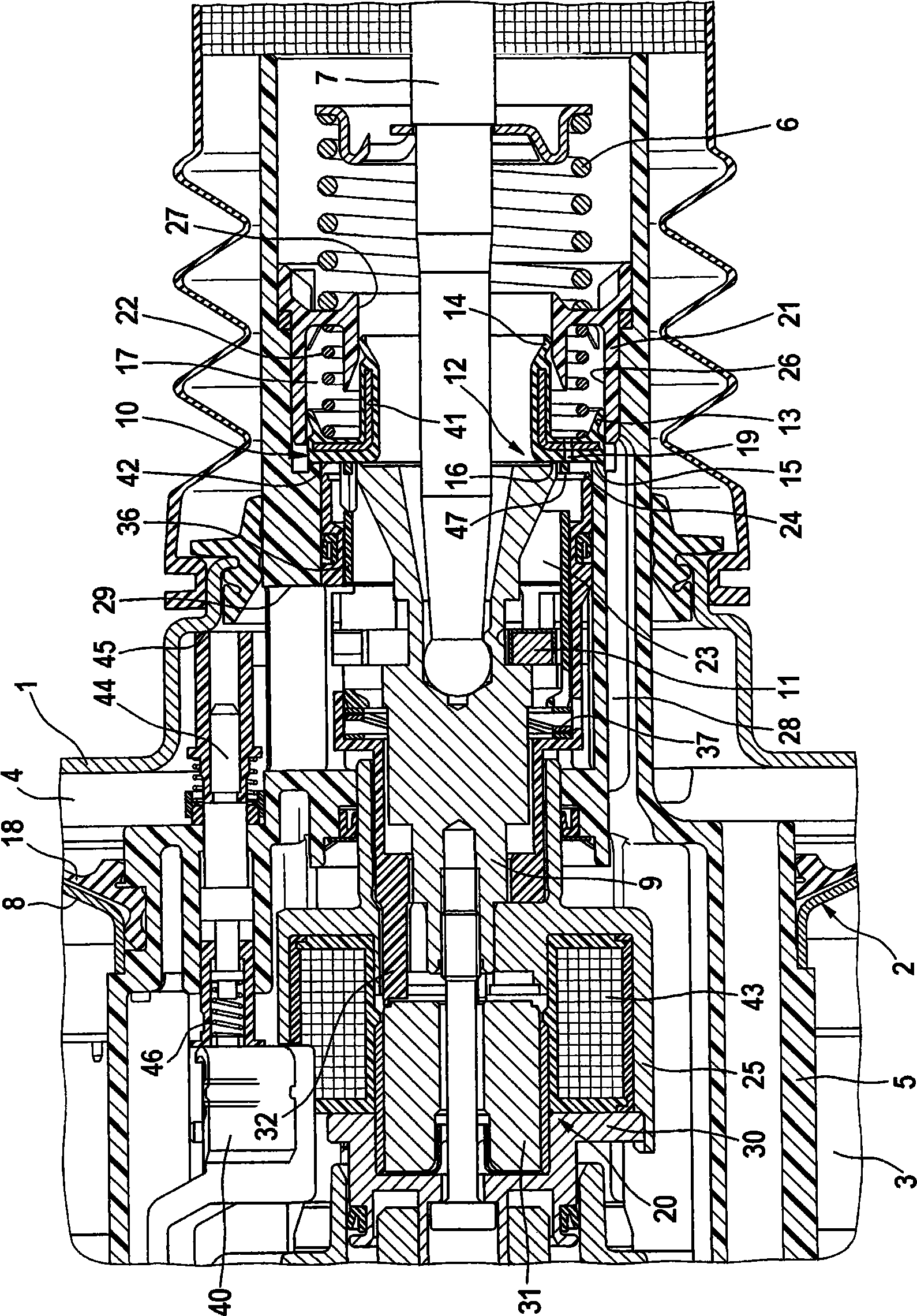
[0016] The only schematically indicated booster housing 1 of the brake booster according to the invention is divided by an axially movable wall 2 into a low-pressure chamber 3 and a working chamber 4 . The axially movable wall 2 comprises a disc-shaped diaphragm 8 made of deep-drawn sheet material and a flexible diaphragm 18 adhering to it. A diaphragm roll acts as a seal between the amplifier housings 1 .

[0017] A control valve 12 operable by means of a joystick 7 is mounted in a controller housing 5 which moves sealingly within the amplifier housing 1 and supports the movable wall 2, said control valve comprising a A first sealing seat 15 formed on the device housing 5, a second sealing seat 16 formed on the valve piston 9 connected to the operating rod 7, and a cooperating with the two sealing seats 15, 16 and on the guide 21 The valve body 10 that moves inside, the guide member is sealed and immovably installed in the controller housing 5, said valve body has an L-shape...


PUM


Abstract

The invention relates to a servobrake for motor vehicles, the control valve (12) of which can be actuated by means of an electromagnet (20), independently of an actuating rod (7) that displaces a valve piston (9), said electromagnet actuating a third seal seat (24) that permits the ventilation of the working chamber (4). The third seal seat (24) is configured on a sleeve (32) that cooperates with the electromagnet (20). An annular element (36), that is arranged so that it can be displaced in relation to the third seal seat (24), is supported on the sleeve (32) by means of an elastic or compressible element (37). According to the invention, in order to improve the noise behaviour of the servobrake, the annular element (36) comprises means for guiding an air flow (L) produced during normal braking in the direction of the working chamber (4).

Description

technical field [0001] The invention relates to a brake booster for motor vehicles, which has: a booster housing, the interior of which is divided by a movable wall into a low-pressure chamber and a working chamber; a controller housing supporting the movable wall, A control valve is arranged in it, which controls the pneumatic pressure difference acting on the movable wall and can be actuated both by means of a valve piston via an actuating lever and independently of the actuating lever by an electromagnet, and the The above-mentioned control valve includes three sealing seats arranged concentrically with each other and a valve body equipped with an axial channel that cooperates with the sealing seats, wherein the first sealing seat is made on the controller housing, and the second sealing seat is made on the valve piston. , and the third sealing seat is made on a sleeve that cooperates with the electromagnet, and an annular member that is movably arranged relative to the thi...

Claims


Application Information

Patent Timeline
Patent Type & Authority Applications(China)
IPC IPC(8): B60T13/57B60T13/72
Inventor S·贝克
Owner CONTINENTAL TEVES AG & CO OHG
Why Eureka
Try Eureka