Flange vibration-pressing coiling forming method and forming device

A vibrating rolling and forming machine technology, applied in metal processing equipment, feeding device, positioning device, etc., can solve the problems of small rolling force, diameter restriction, complexity, etc. high precision effect

Inactive Publication Date: 2009-08-19
高益峰
View PDF5 Cites 2 Cited by
  • Summary
  • Abstract
  • Description
  • Claims
  • Application Information

AI Technical Summary

Problems solved by technology

[0004] CN101279350 patent document discloses a horizontal flange ring rolling machine, which has a large and complex structure, high cost, and difficult control of flange manufacturing precision
[0005] CN201127961Y patent document discloses a flange rolling machine, which is similar to a plate rolling machine, with low pressure, poor efficacy and inconvenient unloading
[0006] And the disclosed flange blank hot rolling machine of CN101342553A patent document, a kind of flange rolling machine disclosed in CN201044934Y patent document, the tight pressure forming flange disclosed in CN1970218A patent document and processing equipment and processing method, all exist the diameter of production flange Restricted by the mold, one mold corresponds to one flange diameter, and molds of various specifications are required to match it. For the flange blank hot coiling machine disclosed in the CN101342553A patent document, there is still heating of the mold, which makes its production cost high problem
For the flange processing equipment and processing method disclosed in the CN1970218A patent document, there is still the problem that there is no guide rail when the pressure roller is pressed down, the stability is poor, the rolling force is small, and only thinner steel plates can be rolled.

Method used


Image

  • Flange vibration-pressing coiling forming method and forming device
  • Flange vibration-pressing coiling forming method and forming device
  • Flange vibration-pressing coiling forming method and forming device

Examples


Embodiment Construction

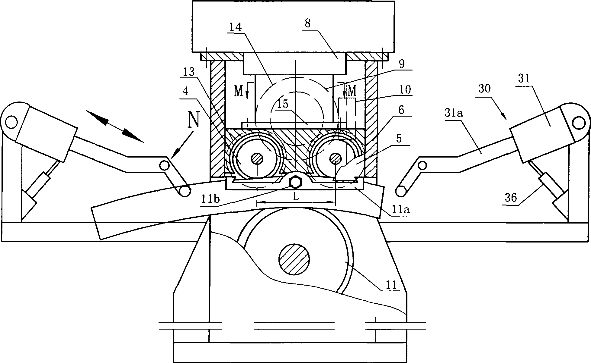
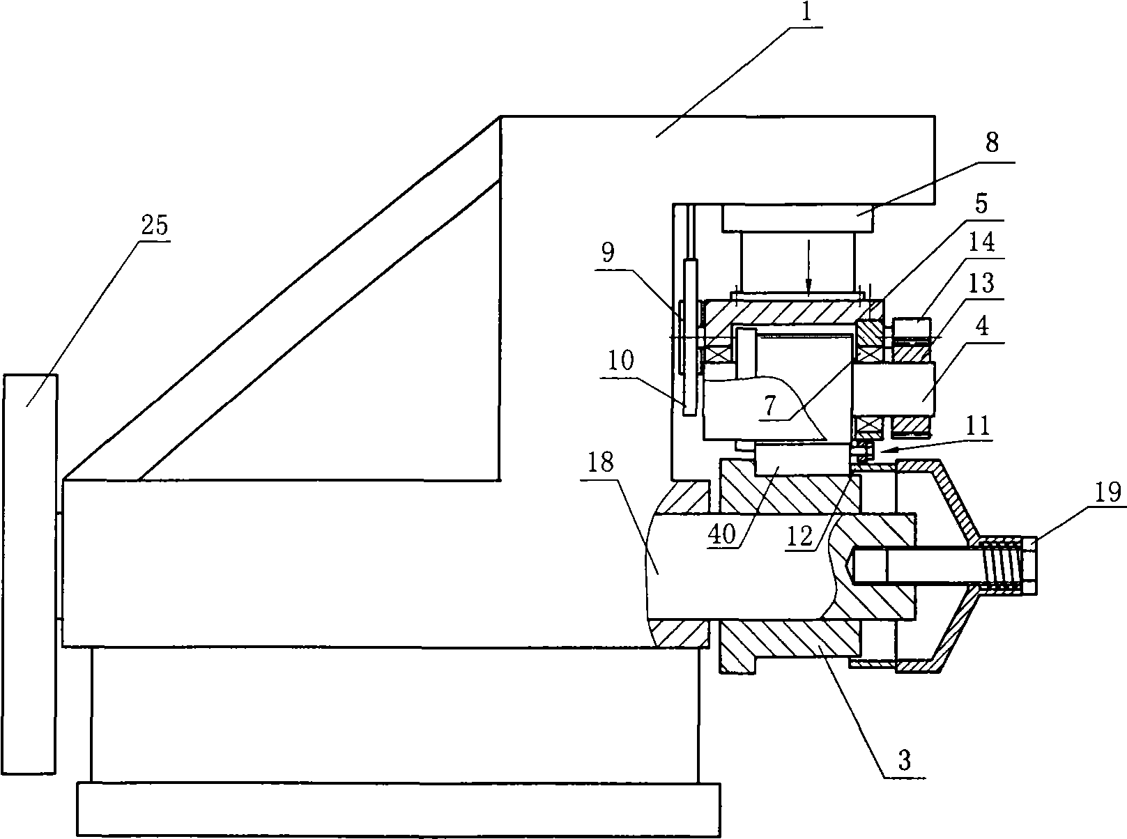
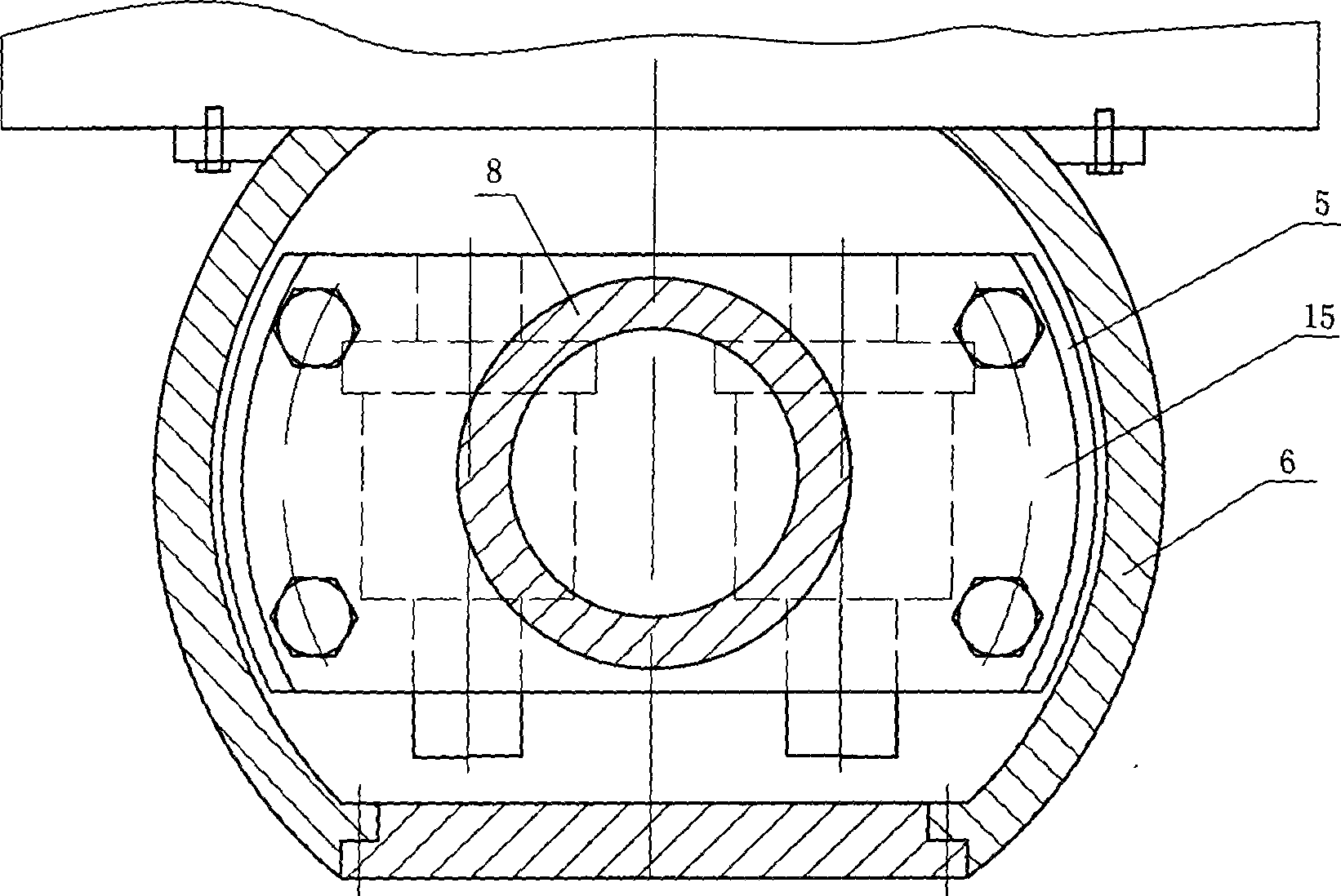
[0035] The flange forming machine of the present invention is mainly composed of fixed rolling die 3, sliding rolling die 4, main hydraulic oil cylinder 8, slider 5, slide rail 6, auxiliary pushing mechanism 10, main hydraulic pump, fixed rolling die driving mechanism, sliding roller Die driving mechanism and vibrating pump, please refer to figure 1 , figure 2 ,. Fixed rolling die is installed in the frame bottom, and two sliding rolling dies 4 are supported in the slide block 5 by corresponding axle and bearing 7, and slide block 5 is slidingly connected in slide rail 6, and slide rail 6 is installed on the top of frame 1. Both sides of the slider 5 are arc surfaces, and the whole is a drum-shaped structure. The rail surfaces on the two slide rails 6 correspond to the arc surfaces on both sides of the slider 5, please refer to image 3 . The main hydraulic pump and the vibration pump (not shown) are connected with the hydraulic cylinder 8 through the oil pipe, and the hy...


PUM


Abstract

The invention relates to a method for forming a flange by vibrating and winding and a forming machine thereof. The forming method comprises the following steps: 1, positioning steel plates to be processed on the forming machine, and moving a sliding rolling die downward to a press initial position A on the upper lateral surface of the steel plate; 2, pressing the steel plate downward for delta h stroke by the sliding rolling die to a press stop position B; 3, feeding the steel plate according to certain speed, making the upper and lower vibration with certain frequency at the position B, and vibrating the steel plate by the sliding rolling die to ensure that the steel plate is bent to the set radian; and 4, trimming a connector of the flange by a head trimming device to finish the forming and winding of the flange. The forming machine comprises a fixing rolling die, the sliding rolling die, a hydraulic oil cylinder, a main hydraulic pump, a vibration pump, a sliding block, a sliding rail and an auxiliary material pushing mechanism; the sliding block is glidingly connected to the sliding rail; the sliding rolling die is connected to the sliding block; the vibration pump is connected with the hydraulic oil cylinder; and the auxiliary material pushing mechanism is connected to the stander and pushes the steel plate to feed when the sliding block and the sliding rolling die make the vibrations. The forming machine has the advantages of low energy consumption, good winding effect and stability, less material consumption and low cost.

Description

technical field [0001] The invention relates to the processing and manufacture of flanges, in particular to a flange vibrating winding forming method and a forming machine thereof. Background technique [0002] Flanges are one of the most important connecting parts of pipelines, and they are in great demand every year. The traditional production method of flange blanks is: gas cutting multiple segments, and then electric welding and splicing. This kind of method not only has poor precision, takes labor and materials, low material utilization rate, high cost and heavy electric welding workload, but electric welding is harmful to the health of operators. [0003] The current flange production has been partially processed by special mechanical rolling. Although the material utilization rate has been greatly improved and the welding workload is small, there are some shortcomings, such as: [0004] The CN101279350 patent document discloses a horizontal flange ring rolling machi...

Claims


Application Information

Patent Timeline
Patent Type & Authority Applications(China)
IPC IPC(8): B21D11/10B21D11/22B21D43/00B21D43/02
Inventor 高益峰
Owner 高益峰
Why Eureka
Try Eureka