Plasma gurney flap

A plasma and plasma technology, which is applied in the field of plasma Gurney flaps, can solve the problems of complex structure and increased resistance of blown Gurney flaps, so as to improve operational economic efficiency, overcome increased resistance and reduce power consumption Effect

Inactive Publication Date: 2009-08-19
BEIHANG UNIV
View PDF1 Cites 29 Cited by
  • Summary
  • Abstract
  • Description
  • Claims
  • Application Information

AI Technical Summary

Problems solved by technology

[0007] The object of the present invention is to propose a plasma Gurney flap, to solve the resistance increase...

Method used


Image

  • Plasma gurney flap
  • Plasma gurney flap
  • Plasma gurney flap

Examples


Embodiment Construction

[0046] The technical solutions of the present invention will be further described below in conjunction with the accompanying drawings and embodiments.

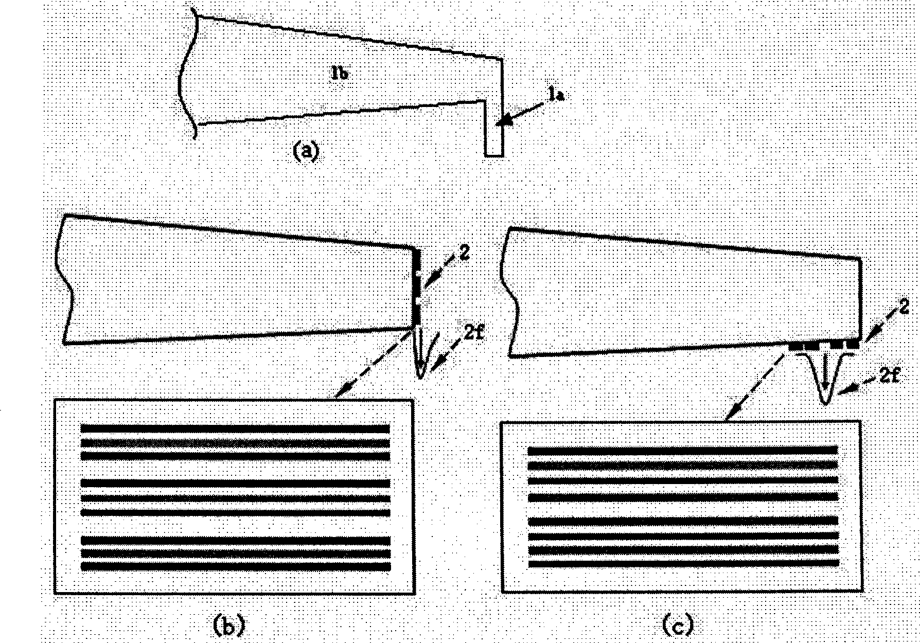
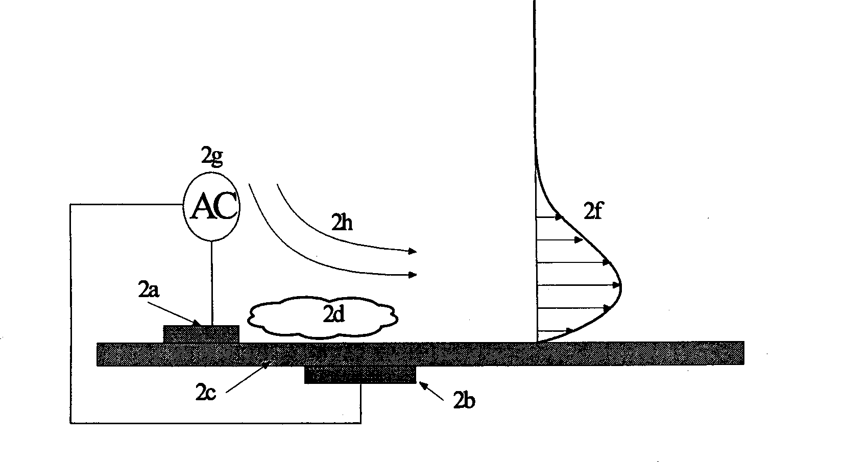
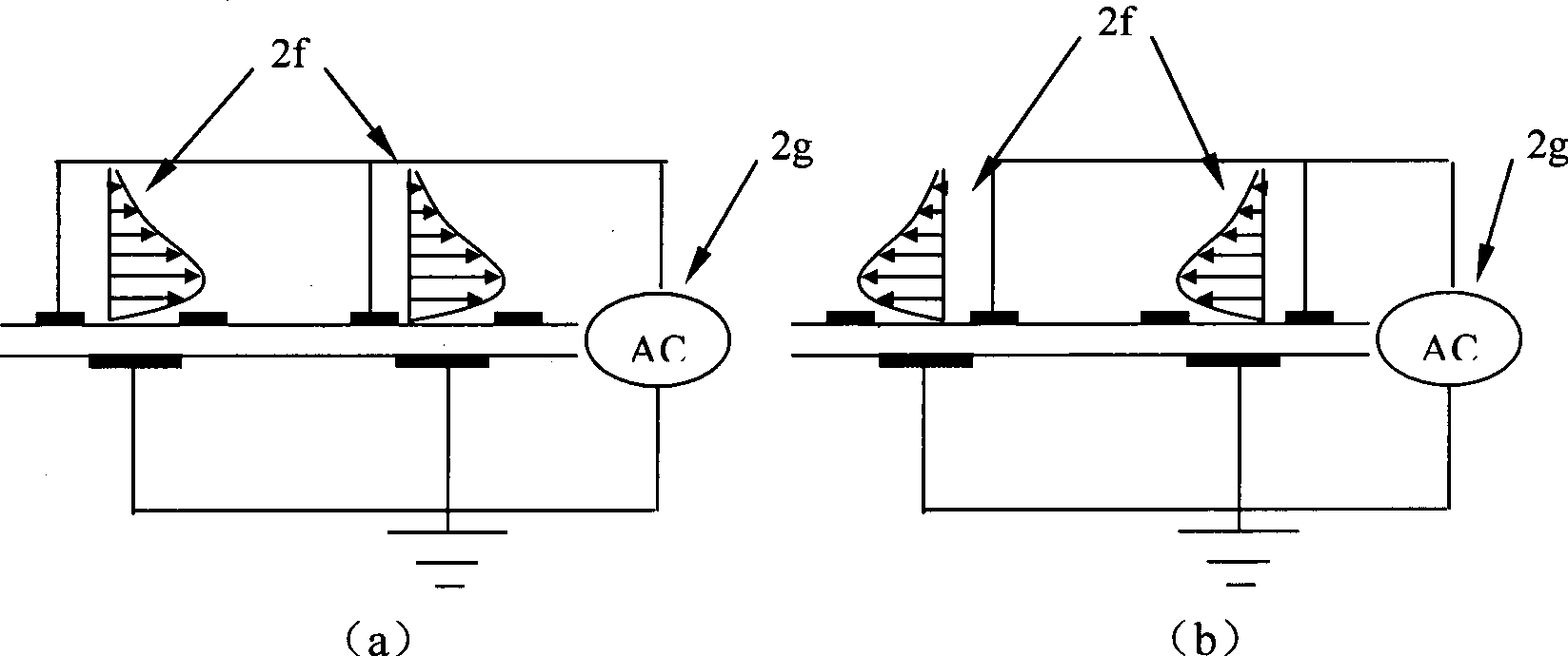
[0047] The invention is a plasma Gurney flap, and the adopted plasma exciter is based on the principle of surface dielectric barrier discharge (DBD). The plasma Gurney flap is to arrange a plasma exciter on the trailing edge or trailing edge pressure surface of the airfoil, and the plasma exciter 2 includes: two electrodes, one electrode (cathode) 2a is directly exposed to the air The other electrode (anode) 2b is buried in the insulating medium 2c; the electrode is made of metal sheet (copper sheet or aluminum sheet), and the size is determined according to the specific situation; the plasma exciter 2 can be made in the form of a printed circuit board , In addition, the insulating medium 2c can adopt polytetrafluoroethylene, epoxy resin, polyimide film (Kapton) or Teflon (teflon), if adopt flexible insulating medium polyimide...


PUM


Abstract

The invention relates to a plasma Gurney flap. The adopted plasma exciter is based on the principle of surface dielectric barrier discharge (DBD). The plasma Gurney flap comprises a single plasma exciter or a plasma exciter bar which is arranged on the airfoil shape trailing edge or the pressure surface at the trailing edge. The plasma exciter comprises two dissymmetrically placed electrodes, one of which (cathode) is exposed in the air directly while the other one (anode) is embedded in an insulating medium, wherein the electrodes are made of sheet metal, and the sizes thereof can be determined according to concrete conditions of application; if the insulating medium adopts polytetrafluoroethylene, epoxy resin, and the like, the plasma exciter can be made by adopting a printed circuit board; if the insulating medium adopts flexible insulating materials such as Kapton, Teflon, and the like, the plasma exciter can be made in a pasting mode; and the flexible insulating materials can adapt to different shapes of the airfoil trailing edge, thus the plasma Gurney flap is quite simple and convenient and is convenient to maintain.

Description

Technical field: [0001] The invention relates to a plasma Gurney flap, in particular, it can be applied to the trailing edge of the wing or airfoil to replace the traditional mechanical Gurney flap or blown Gurney flap, to increase the lift of the aircraft or provide flight control The plasma gurney flap. Background technique: [0002] Such as figure 1 As shown in (a), the traditional mechanical Gurney flap 1a is a small spoiler located on the lower surface of the trailing edge of the airfoil 1b and installed perpendicular to the chord line of the airfoil. This simple trailing edge device can achieve the same effect as the complex high-lift system, effectively improving the lift characteristics of the airfoil. [0003] The existing research results show that as long as the Gurney flap exists, no matter it is two-dimensional or three-dimensional, it will increase the drag of the airfoil. Therefore, in order to apply this simple and effective high-lift device to actual engi...

Claims


Application Information

Patent Timeline
IPC IPC(8): B64C9/00B64C13/00
Inventor 张攀峰王晋军刘爱兵崔宏昭
Owner BEIHANG UNIV
Why Eureka
Try Eureka