Hollow mold for filling cast-in-situ concrete

A technology of hollow carcass and cast-in-place concrete, which is applied in the direction of building materials, building components, floor slabs, etc., and can solve the problems affecting the construction quality of hollow floors, affecting the construction quality of floors, and the inability to arrange hollow carcass, etc., so as to achieve simple design , Simple structure, excellent anti-vibration performance

Inactive Publication Date: 2009-08-19
湖南邱则有专利战略策划有限公司
View PDF3 Cites 1 Cited by
  • Summary
  • Abstract
  • Description
  • Claims
  • Application Information

AI Technical Summary

Problems solved by technology

But when this kind of hollow carcass is applied to the floor construction, the hollow carcass cannot be accurately arranged in the middle layer of the floor, which affects the construction quality of the floor
For this reason, the patent number is ZL01215092.4, and the utility model patent titled "Building Components" discloses a building component that is a polyhedron, which can be hollow or solid. It is arranged in the middle layer of the floor, and the outer wall of the polyhedron is provided with protruding legs, so that when the floor is poured, the legs can ensure that the hollow multi-faceted main cavity is just at the middle layer of the floor. , so as to better solve the above problems. However, the positioning of this building component is inconvenient during construction and layout, and it is prone to misalignment, which affects the construction quality of the hollow floor and affects the construction efficiency. Therefore, a new type of existing The hollow carcass used for pouring concrete filling is urgently needed

Method used


Image

  • Hollow mold for filling cast-in-situ concrete
  • Hollow mold for filling cast-in-situ concrete
  • Hollow mold for filling cast-in-situ concrete

Examples


Embodiment Construction

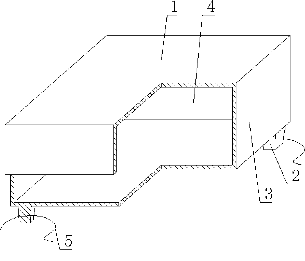
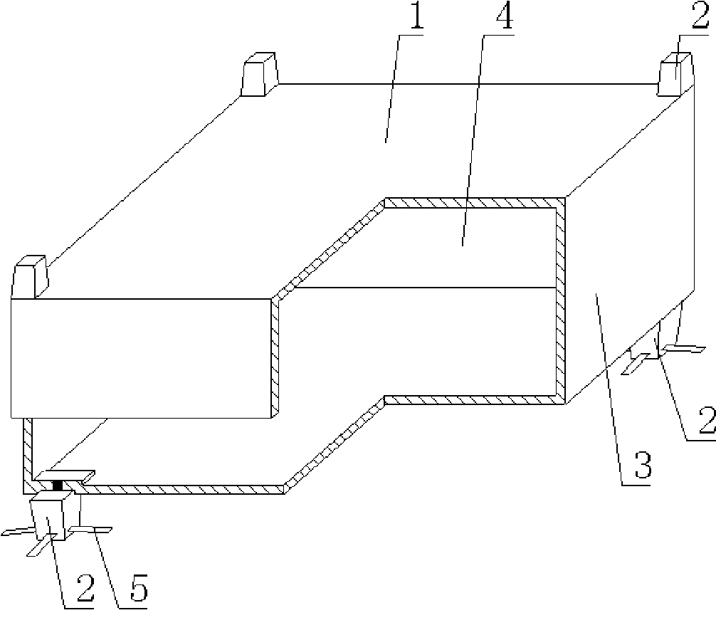
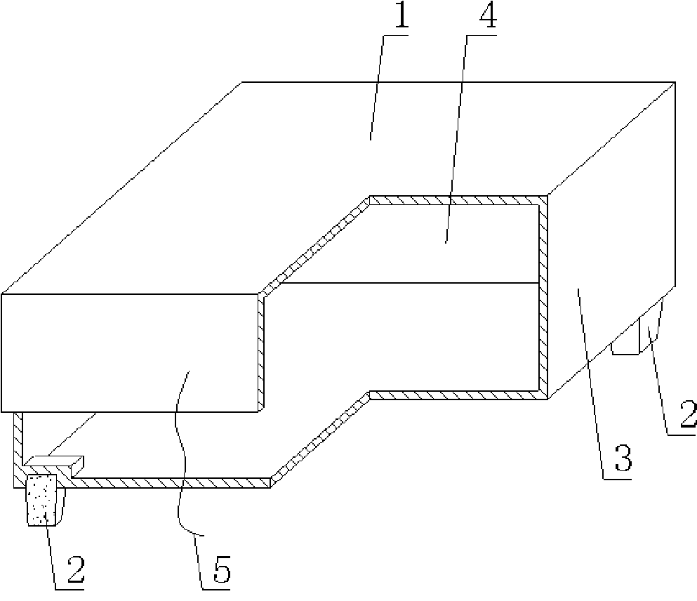
[0070] The present invention will be further described below in conjunction with the drawings and embodiments.

[0071]As shown in the drawings, the present invention includes a hollow carcass 1 and supporting feet 2. The supporting legs 2 are arranged on the bottom outer wall 3 of the hollow carcass 1. The outer wall 3 encloses the hollow carcass 1 with a cavity 4, and is characterized by The supporting leg 2 is provided with a fixed or separate positioning anti-floating member 5, the positioning anti-floating member 5 passes through the supporting leg 2, and extends out of the supporting leg 2 to be exposed. The supporting leg 2 is a fixed foot or a hollow carcass 1 is a polyhedron. In the drawings, 1 is a hollow carcass, 2 is a support foot, 3 is an outer wall, 4 is a cavity, and 5 is a positioning anti-floating member. In the following drawings, the same numbers have the same descriptions. Such as figure 1 As shown, the outer wall 3 encloses the hollow carcass 1 formed with a...


PUM


Abstract

A hollow matrix for filling cast-in-situ concrete comprises a hollow matrix (1) and a supporting lug (2), wherein, the supporting lug (2) is arranged at the bottom external wall (3) of the hollow matrix (1), the external wall (3) is enclosed to form the hollow matrix (1) with a hollow chamber (4); the characteristics lie in that: the supporting lug (2) is provided with a fixed or separated positioning anti-floating component (5), the anti-floating component (5) penetrates the supporting lug (2) and extends out of the supporting lug (2), the supporting lug (2) is a fixed, or the hollow roughcast is a polytope. Move dislocation and floating upward of the hollow matrix can be effectively avoided, and the concreting quality of the cast-in-situ floor systems can be greatly improved. The hollow matrix for filling cast-in-situ concrete is suitable for the hollow plates, floor systems, roofs, walls, foundation bottom boards and bridges made of cast-in-situ reinforced concrete or prestressed reinforced concrete and is suitable for hollow girderless floor systems in particular.

Description

[0001] This application is a divisional application of the invention patent application whose application date is August 12, 2004, the application number is 2004101552212, and the name is "a hollow carcass for in-situ concrete filling". (1) Technical field [0002] The invention relates to a hollow carcass for in-situ concrete filling. (2) Background technology [0003] At present, cast-in-situ concrete hollow floor is a widely used floor structure. The lightweight permanent tire mold filled in it has various hollow tubes and boxes, and the boxes are hollow or solid. For example, the applicant applied for a patent number ZL99249798.1 on November 29, 1999, a utility model patent named "fiber-reinforced thin-walled member for reinforced concrete filling", which discloses a thin-walled formwork member including an upper plate, The surrounding side walls, the lower bottom, the upper plate, the surrounding side walls and the lower bottom enclose a polyhedral cavity. Another example is ...

Claims


Application Information

Patent Timeline
IPC IPC(8): E04C1/00E04B5/18E04B5/36E04C1/39E04C1/40
Inventor 邱则有
Owner 湖南邱则有专利战略策划有限公司
Why Eureka
Try Eureka