Bias electric sounding apparatus and bias electric sounding method

An electrical method and electrical measurement technology, applied in the field of electrical prospecting, can solve the problems of long time spent on wiring, unsatisfactory exploration efficiency, and slow efficiency of exploration measurement, so as to save measurement time and reduce electromagnetic coupling effect, the effect of avoiding technical problems

Inactive Publication Date: 2009-08-19
INST OF GEOLOGY & GEOPHYSICS CHINESE ACAD OF SCI
View PDF0 Cites 10 Cited by
  • Summary
  • Abstract
  • Description
  • Claims
  • Application Information

AI Technical Summary

Problems solved by technology

[0007] The disadvantage of this electrical detection device in the prior art is that even if a multi-channel electrical receiver is used, the detection efficiency is still unsatisfactory
This is because, in the process of on...

Method used


Image

  • Bias electric sounding apparatus and bias electric sounding method
  • Bias electric sounding apparatus and bias electric sounding method
  • Bias electric sounding apparatus and bias electric sounding method

Examples


Embodiment 1

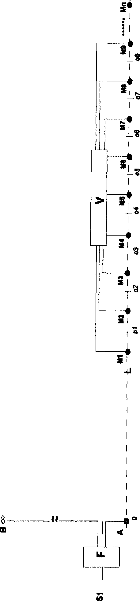
[0033] refer to figure 2 , figure 2A schematic structural diagram showing the field construction arrangement of an exemplary embodiment of the electrical detection device of the present invention. Such as figure 2 As shown in , an exemplary offset electrical detection device according to the present invention includes: an electrical transmitter F for providing a measurement current and an electrical receiver V for measurement. The electrical method transmitter F includes a near-end power supply electrode A and a far-end power supply electrode B (or called an infinitely distant electrode), and it is expected that the far-end power supply electrode B is arranged at an infinite distance from the near-end power supply electrode A, In actual implementation, considering the feasibility of the operation method, the far-end power supply electrode B is generally arranged at a distance of 1.5km or more from the proximal power supply electrode (A) (the distance of the "infinity" pol...

Embodiment 2

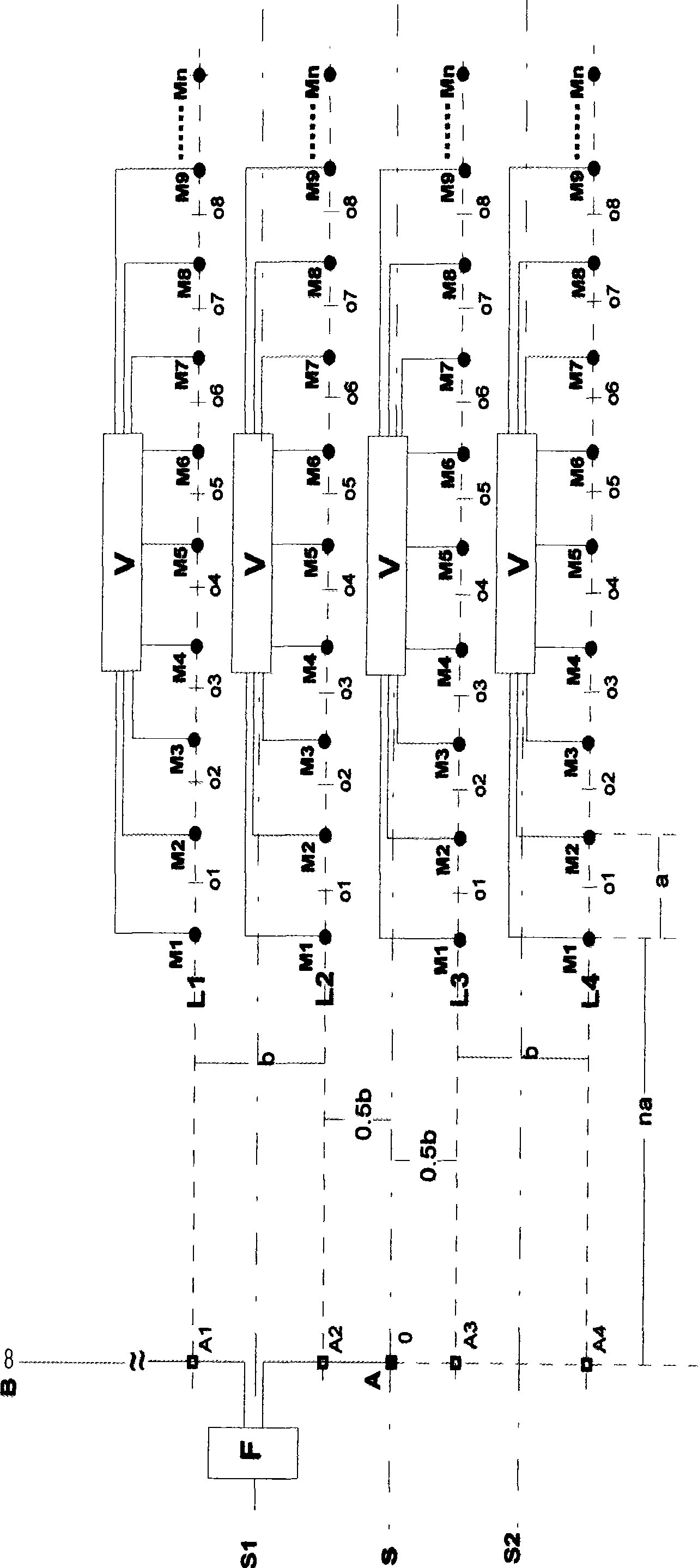
[0052] Figure 4 It is a structural schematic diagram of the field construction arrangement of another exemplary embodiment of the electrical detection device according to the present invention. Figure 4 and figure 2 Similar, except that, figure 2 There are four sets of electrical receivers, and Figure 4 There are three sets of electrical receivers; in addition, figure 2 Each set of electrical receivers has n electrodes, and Figure 4 The number of electrodes in the electrical receiver is different, for example, 9, 8, and 7 electrodes are exemplarily shown to form 8, 7, and 6 channels respectively. In addition, the test line L1 coincides with the layout baseline S, and L2 and L3 deviate from the layout power supply baseline by a distance b.

Embodiment 3

[0054] Figure 5 It is a structural schematic diagram of the field construction arrangement of another exemplary embodiment of the electrical detection device according to the present invention. Figure 5 and figure 2 , Figure 4 Similar, except that, Figure 5 There are three sets of electrical receivers in which the distances between the first measuring electrode (left-hand side in the figure) and the projection points A2 and A3 of the power supply electrode A on the test lines L2 and L3 are not equal. In addition, those skilled in the art should understand that the distance is not strictly limited, and generally can be selected according to experience.


PUM


Abstract

The invention discloses an offset electrical sounding device, comprising an electrical transmitter (F), at least two sets of electrical receiver (V) and an offset processor; wherein the electrical transmitter (F) is used for supplying measuring current, the electrical receiver (V) includes a plurality of measuring electrodes which are parallel to power-supply baselines arranged in an area to be investigated and are arranged with certain reasonable offset distance, and based on the distance between vertical projecting points of the offset distance and an proximal end power-supply electrode to the respective measuring lines and the measuring electrodes, and the distance between two adjacent measuring electrodes (measuring dipoles) which are used for obtaining readings, the offset processor is used for correcting the offsets of data read from the at least two sets of electrical receiver (V), thus obtaining the final corrected measuring reading. The invention also provides an offset electrical sounding method. By utilizing the device and the method, the measuring efficiency can be greatly improved.

Description

technical field [0001] The invention relates to the field of electrical prospecting, in particular to an offset electrical sounding device, which is used for rapid measurement in electrical prospecting; the invention also provides an offset electrical sounding method. Background technique [0002] The direct current method is a branch of the electrical prospecting field. Long-term practice has proved that the direct current method is one of the important methods for exploring groundwater resources and various metal mineral resources. [0003] There are a variety of electrical detection devices in the prior art. The axial measurement method is mainly used for electrical bathymetry measurement, that is, the axis position where the power supply electrode is located (the baseline of the movement of the power supply electrode or the straight line formed by two power supply electrodes) and the position of the survey line where the measurement electrode is located are A straight l...

Claims


Application Information

Patent Timeline
IPC IPC(8): G01V3/02G01V3/38
Inventor 于昌明刘建明曾庆栋叶杰
Owner INST OF GEOLOGY & GEOPHYSICS CHINESE ACAD OF SCI
Why Eureka
Try Eureka