Self-adapting de-interleave method for movement compensation accessory movement

A motion compensation and de-interlacing technology, applied in the field of de-interlacing, can solve problems such as multi-memory computing units, application limitations, and complex operations

Inactive Publication Date: 2009-08-19
XI AN JIAOTONG UNIV
View PDF0 Cites 17 Cited by
  • Summary
  • Abstract
  • Description
  • Claims
  • Application Information

AI Technical Summary

Problems solved by technology

However, the motion compensation de-interlacing method is complex in calculation and requires more memory and computing units, so the hardware cost is high and real-time processing is difficult
Therefore, the application of motion compensation deinterlacing methods in real-time video processing systems is still subject to many restrictions, and has not become the mainstream in the cost-competitive consumer electronics market.

Method used


Image

  • Self-adapting de-interleave method for movement compensation accessory movement
  • Self-adapting de-interleave method for movement compensation accessory movement
  • Self-adapting de-interleave method for movement compensation accessory movement

Examples


Embodiment Construction

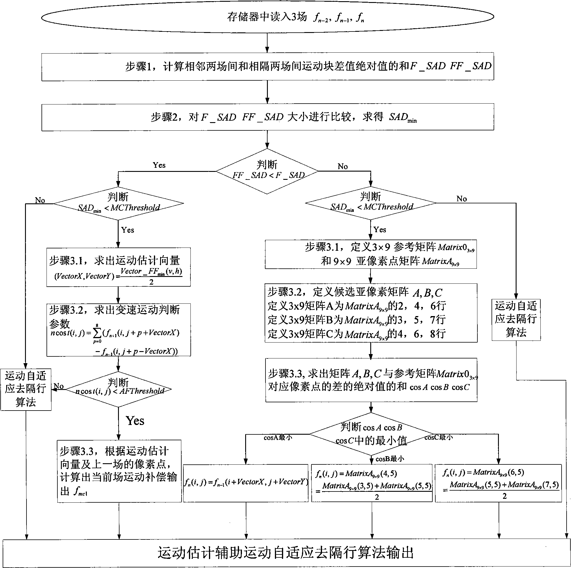
[0039] Such as figure 1 As shown, the motion compensation assisted motion adaptive deinterlacing method of the present invention includes:

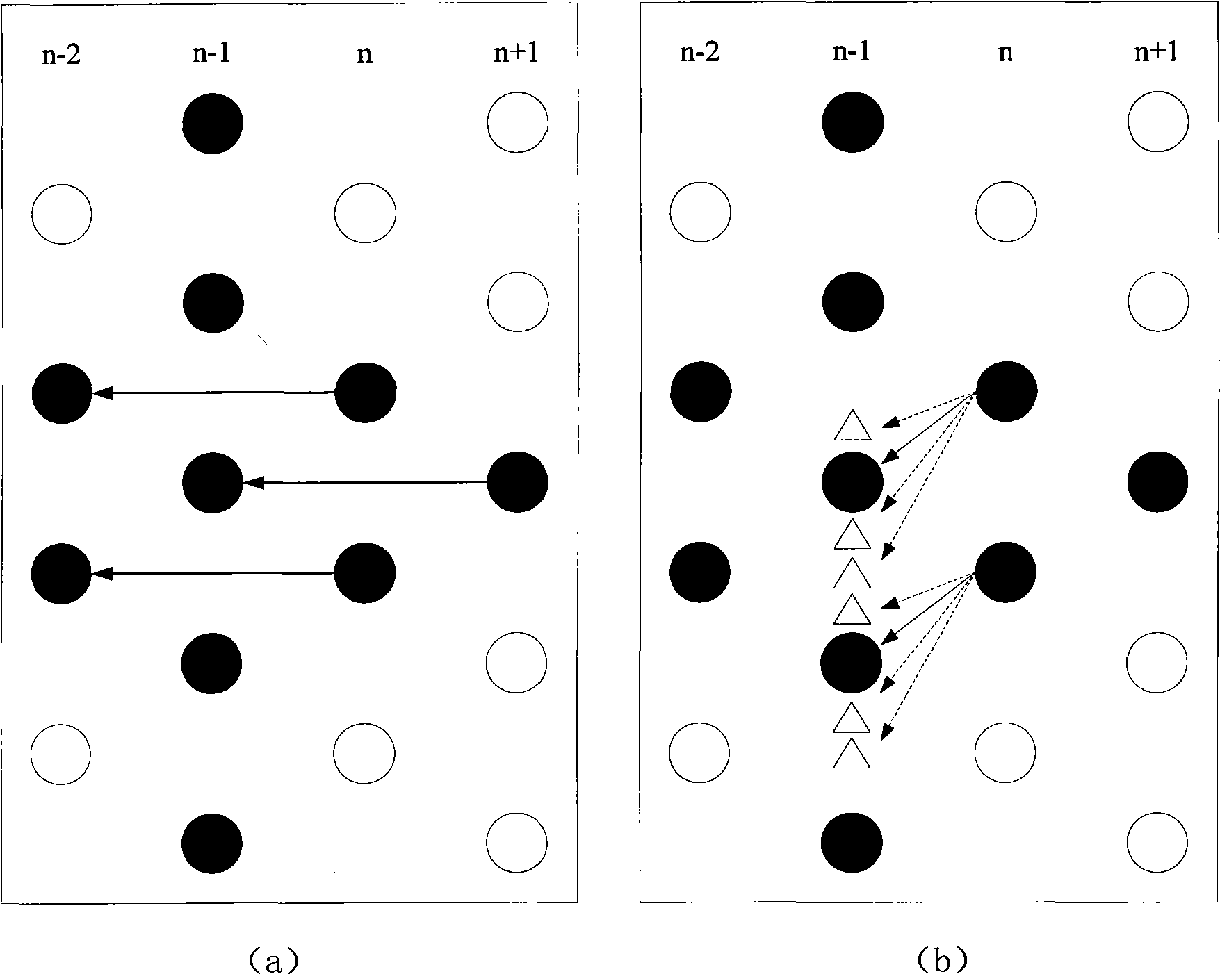
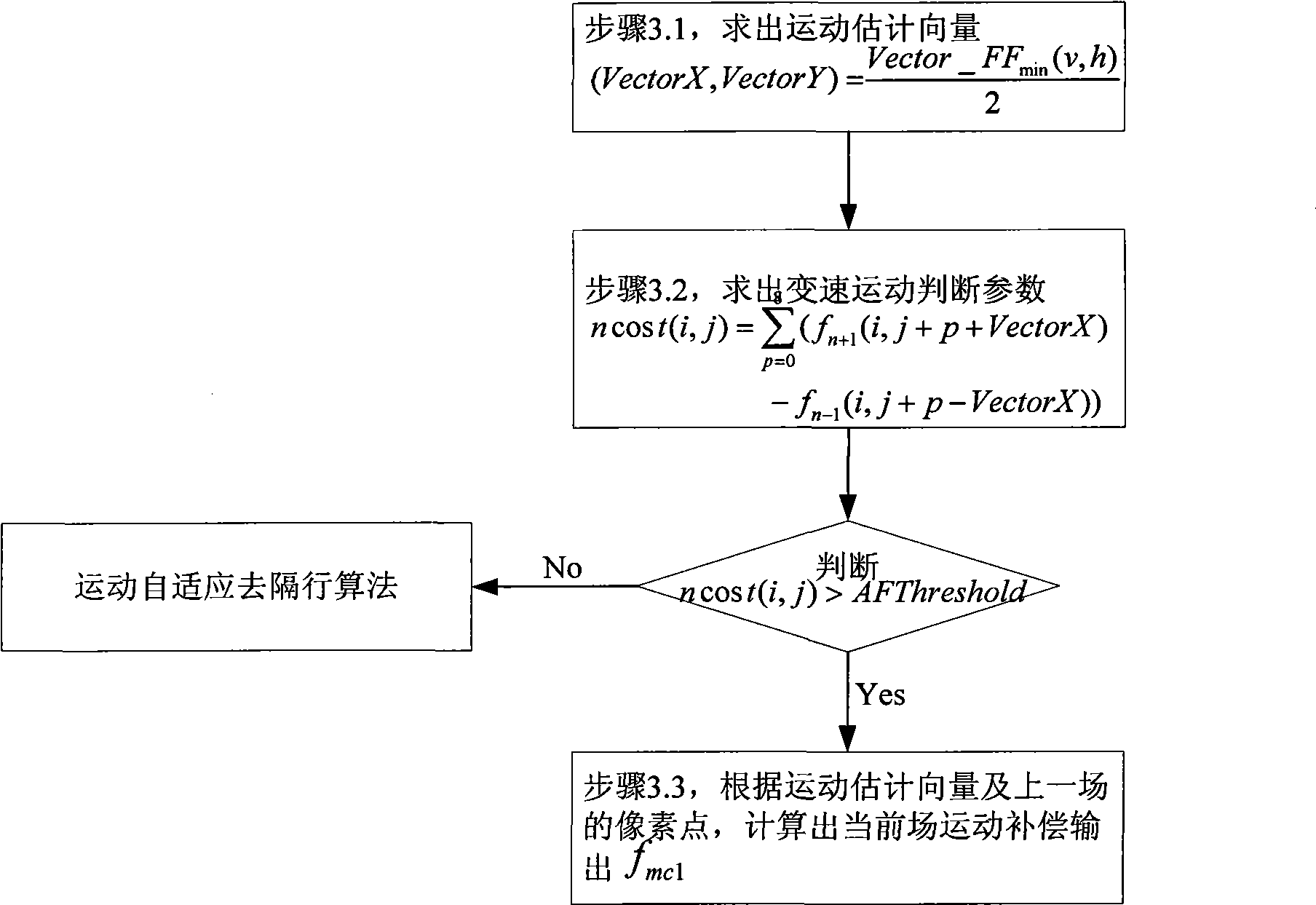
[0040] Step 1: In the current field to be inserted f n The homopolar field f n-2 Find the horizontal motion vector in the current field to be inserted f n The dissimilar polarity field f n-1 Find the vertical motion vector in , such as figure 2 shown. Since the motion compensation de-interlacing in the present invention only deals with slow-moving objects that are more sensitive to the human eye, the search area of ​​the motion vector is much smaller than that of the traditional motion estimation, and the reasonable value range is 24 pixels horizontally and 7 pixels vertically.

[0041] Step 1.1: Divide the entire image of the current field into 10800 (NTSC system) or 12960 (PAL system) 4×8 motion estimation blocks according to different systems,

[0042] Assume that in the current field f n interpolation point f n (i,j) is loca...


PUM


Abstract

The invention discloses a motion compensation accessory movement self adaptive de-interlacing method, which aims at the fact that the visual system of human eye is very sensitive to slow motion and has high resolving capability to the slow motion and for the objects in slow motion, the motion compensation deals based on motion estimation are carried on, while for the objects in fast motion, to which human eye is not sensitive, the movement self adaptive interlacing deals which are characterized by easy hardware implementation are carried on. As motion compensation arithmetic only focuses on the treatment of objects in slow motion, the invention can greatly reduce the complexity of the arithmetic and the corresponding hardware design cost. At the same time, on the base of analyzing interlacing video sampling characteristics, the invention optimizes the compensation arithmetic of classic motion, which puts forward that in different polarity fields, horizontal and vertical motion vectors should be found and the sub-pixel compensation method should be used for improving the definition of images in vertical direction aiming at the deadly defect that in the process of interlacing sampling, the definition of image in vertical direction is seriously influenced.

Description

technical field [0001] The invention relates to a de-interlacing method in computing video and digital television post-processing, in particular to a video de-interlacing method utilizing motion compensation of human visual characteristics to assist motion self-adaptation. Background technique [0002] With the emergence of high-definition large-screen display devices with progressive scan format such as high-definition TV, LCD TV LCD, PC video, rear-projection TV, and plasma TV (PDP), the traditional interlaced scanning technology is inherently The phenomenon of damaging image quality cannot be eliminated due to the characteristic, which can no longer meet people's current needs. Therefore, in the transition stage where interlaced and progressive scanning technologies coexist, there is a wide demand for format conversion of video signals between different transmission and display devices. [0003] De-interlacing processing technology is an indispensable part of the video s...

Claims


Application Information

Patent Timeline
Patent Type & Authority Applications(China)
IPC IPC(8): H04N7/01H04N5/44
Inventor 孙宏滨郑南宁葛晨阳罗亮卢开芳张超
Owner XI AN JIAOTONG UNIV
Why Eureka
Try Eureka